- Digital Electronics - Home
- Digital Electronics Basics
- Types of Digital Systems
- Types of Signals
- Logic Levels And Pulse Waveforms
- Digital System Components
- Digital Logic Operations
- Digital Systems Advantages
- Number Systems
- Number Systems
- Binary Numbers Representation
- Binary Arithmetic
- Signed Binary Arithmetic
- Octal Arithmetic
- Hexadecimal Arithmetic
- Complement Arithmetic
- Base Conversions
- Base Conversions
- Binary to Decimal Conversion
- Decimal to Binary Conversion
- Binary to Octal Conversion
- Octal to Binary Conversion
- Octal to Decimal Conversion
- Decimal to Octal Conversion
- Hexadecimal to Binary Conversion
- Binary to Hexadecimal Conversion
- Hexadecimal to Decimal Conversion
- Decimal to Hexadecimal Conversion
- Octal to Hexadecimal Conversion
- Hexadecimal to Octal Conversion
- Binary Codes
- Binary Codes
- 8421 BCD Code
- Excess-3 Code
- Gray Code
- ASCII Codes
- EBCDIC Code
- Code Conversion
- Error Detection & Correction Codes
- Logic Gates
- Logic Gates
- AND Gate
- OR Gate
- NOT Gate
- Universal Gates
- XOR Gate
- XNOR Gate
- CMOS Logic Gate
- OR Gate Using Diode Resistor Logic
- AND Gate vs OR Gate
- Two Level Logic Realization
- Threshold Logic
- Boolean Algebra
- Boolean Algebra
- Laws of Boolean Algebra
- Boolean Functions
- DeMorgan's Theorem
- SOP and POS Form
- POS to Standard POS Form
- Minimization Techniques
- K-Map Minimization
- Three Variable K-Map
- Four Variable K-Map
- Five Variable K-Map
- Six Variable K-Map
- Don't Care Condition
- Quine-McCluskey Method
- Min Terms and Max Terms
- Canonical and Standard Form
- Max Term Representation
- Simplification using Boolean Algebra
- Combinational Logic Circuits
- Digital Combinational Circuits
- Digital Arithmetic Circuits
- Multiplexers
- Multiplexer Design Procedure
- Mux Universal Gate
- 2-Variable Function Using 4:1 Mux
- 3-Variable Function Using 8:1 Mux
- Demultiplexers
- Mux vs Demux
- Parity Bit Generator and Checker
- Comparators
- Encoders
- Keyboard Encoders
- Priority Encoders
- Decoders
- Arithmetic Logic Unit
- 7-Segment LED Display
- Code Converters
- Code Converters
- Binary to Decimal Converter
- Decimal to BCD Converter
- BCD to Decimal Converter
- Binary to Gray Code Converter
- Gray Code to Binary Converter
- BCD to Excess-3 Converter
- Excess-3 to BCD Converter
- Adders
- Half Adders
- Full Adders
- Serial Adders
- Parallel Adders
- Full Adder using Half Adder
- Half Adder vs Full Adder
- Full Adder with NAND Gates
- Half Adder with NAND Gates
- Binary Adder-Subtractor
- Subtractors
- Half Subtractors
- Full Subtractors
- Parallel Subtractors
- Full Subtractor using 2 Half Subtractors
- Half Subtractor using NAND Gates
- Sequential Logic Circuits
- Digital Sequential Circuits
- Clock Signal and Triggering
- Latches
- Shift Registers
- Shift Register Applications
- Binary Registers
- Bidirectional Shift Register
- Counters
- Binary Counters
- Non-binary Counter
- Design of Synchronous Counter
- Synchronous vs Asynchronous Counter
- Finite State Machines
- Algorithmic State Machines
- Flip Flops
- Flip-Flops
- Conversion of Flip-Flops
- D Flip-Flops
- JK Flip-Flops
- T Flip-Flops
- SR Flip-Flops
- Clocked SR Flip-Flop
- Unclocked SR Flip-Flop
- Clocked JK Flip-Flop
- JK to T Flip-Flop
- SR to JK Flip-Flop
- Triggering Methods:Flip-Flop
- Edge-Triggered Flip-Flop
- Master-Slave JK Flip-Flop
- Race-around Condition
- A/D and D/A Converters
- Analog-to-Digital Converter
- Digital-to-Analog Converter
- DAC and ADC ICs
- Realization of Logic Gates
- NOT Gate from NAND Gate
- OR Gate from NAND Gate
- AND Gate from NAND Gate
- NOR Gate from NAND Gate
- XOR Gate from NAND Gate
- XNOR Gate from NAND Gate
- NOT Gate from NOR Gate
- OR Gate from NOR Gate
- AND Gate from NOR Gate
- NAND Gate from NOR Gate
- XOR Gate from NOR Gate
- XNOR Gate from NOR Gate
- NAND/NOR Gate using CMOS
- Full Subtractor using NAND Gate
- AND Gate Using 2:1 MUX
- OR Gate Using 2:1 MUX
- NOT Gate Using 2:1 MUX
- Memory Devices
- Memory Devices
- RAM and ROM
- Cache Memory Design
- Programmable Logic Devices
- Programmable Logic Devices
- Programmable Logic Array
- Programmable Array Logic
- Field Programmable Gate Arrays
- Digital Electronics Families
- Digital Electronics Families
- CPU Architecture
- CPU Architecture
Types of Signals
In electronics engineering, an electrical quantity like voltage or current or electromagnetic wave that is used for transmission of data or information is called a signal.
Signals are considered the heart of any data communication or processing system like the Internet. Signals instruct the electronics hardware components to perform a certain task such as convey the information from one point to another.
Apart from voltage, current or electromagnetic signals, we also have optical signals, where the information is represented and transmitted in the form of light.
This chapter will explain the concept of signal and different types of signals used in electronics engineering.
What is a Signal?
A physical quantity that has capability to transmit information from one point to another is called a signal. Some common examples of signals include voltage, current, electromagnetic wave, optical signals, etc.
Signals are the backbone of any electronic processing or communication system. These can be transmitted through various types of communication channels like wires, space (electromagnetic waves), optical fibers, etc.
Properties of Signal
In electronics, a signal is characterized by the following important properties −
- Magnitude − The intensity or maximum value of a signal is termed as its magnitude.
- Frequency − The number of oscillations per second is called frequency of the signal.
- Time period − The time taken to complete one oscillation is called the time period of the signal.
Types of Signals
In electronics, there are mainly two types of signals used, they are −
- Analog Signals
- Digital Signals
Let us discuss these two types of signals in detail.
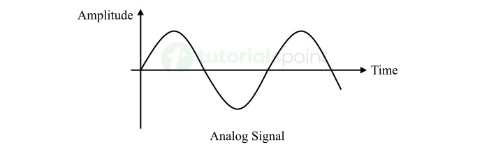
What is an Analog Signal?
A type of electronic signal that has continuous values within a given range is called an analog signal. Analog signals are expressed as the continuous functions of time. They are represented as the waveforms of continuously varying current or voltage.
Example of analog signals are voice, speed, pressure, temperature, etc.
An important characteristic of analog signals is that they have a definite value at every instant of time, known as instantaneous value of the signal.
Analog signals have smooth waveforms as they are continuous in both amplitude and time. That meant, there is no interruptions in their representation over time.
Properties of Analog Signal
The following are main properties of analog signals −
- Analog signals are continuous signals in both amplitude and time.
- Analog signals have a certain value or magnitude at any given instant of time.
- Analog signals have infinite resolution.
- Analog signals are best suited for representing the real-world phenomena.
- Analog signals are represented by the continuously varying smooth waveforms.
What is a Digital Signal?
A digital signal is a type of electronic signal that has a finite set of discrete values representing information.
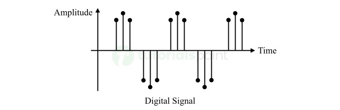
Digital signals are also called binary signals, as they use binary 0 or 1 to represent the state of a signal. Where, the binary 0 represents the off or low state of the signal, while the binary 1 represents the on or high state of the signal.
Thus, digital signals are expressed as discontinuous functions of time.
Properties of Digital Signal
The following are some key characteristics of digital signals −
- Digital signals have discrete or discontinuous values in terms of both amplitude and time.
- Digital signals do not have values defined between any two distinct instants of time.
- Digital signals are represented using binary system by sampling the values of the signals at specific time instants.
- Digital signals represent information in the form of a sequence of binary 0s and 1s.
- Digital signals have a finite resolution.
- Digital signals are capable to perform logical operations.
- Digital signals are more efficient and reliable when it comes to storage and transmission.
Difference between Analog and Digital Signals
Let us now discuss the important differences between analog and digital signals −
| Key | Analog Signals | Digital Signals |
|---|---|---|
| Representation | Analog signals are represented as continuous functions or waveforms of time. | Digital signals are represented as discrete functions of time. |
| Nature | Analog signals are continuous as they have infinite values within a specified range. | Digital signals are discontinuous as they have distinct values sampled at specific time instants. |
| Resolution | Analog signals have infinite resolution. | Digital signals have a finite resolution. |
| Accuracy | Analog signals are more accurate. | Digital signals are relatively less accurate. |
| Storage | Analog signals are difficult to store. | Digital signals are efficient to store. |
| Noise immunity | Analog signals are less immune to noise. | Digital signals have high immunity against noise. |
| Examples | Voice signals, temperature, speed, etc. | Data transmitted over internet, computer generated signals, etc. |
Applications of Signals
Both analog and digital signals are widely used in the field of electronics. The following are some key applications of signals −
- Signals are used for storage and transmission of information.
- Signals are used in control systems to regulate their behavior.
- Signals are also used in measurement of physical quantities like temperature, pressure, speed, sound, light, and more.
- Signals are used in computing systems for data processing, etc.
Conclusion
In electronics engineering, signals are most significant elements of a system. Signals are nothing but physical quantities like voltage, current, electromagnetic waves, light pulses, etc. used to convey information from one point to another.
In this chapter, we covered different types of signals and their properties. In the next chapter, we will cover the concept of logic levels and pulse waveform.
