- Digital Electronics - Home
- Digital Electronics Basics
- Types of Digital Systems
- Types of Signals
- Logic Levels And Pulse Waveforms
- Digital System Components
- Digital Logic Operations
- Digital Systems Advantages
- Number Systems
- Number Systems
- Binary Numbers Representation
- Binary Arithmetic
- Signed Binary Arithmetic
- Octal Arithmetic
- Hexadecimal Arithmetic
- Complement Arithmetic
- Base Conversions
- Base Conversions
- Binary to Decimal Conversion
- Decimal to Binary Conversion
- Binary to Octal Conversion
- Octal to Binary Conversion
- Octal to Decimal Conversion
- Decimal to Octal Conversion
- Hexadecimal to Binary Conversion
- Binary to Hexadecimal Conversion
- Hexadecimal to Decimal Conversion
- Decimal to Hexadecimal Conversion
- Octal to Hexadecimal Conversion
- Hexadecimal to Octal Conversion
- Binary Codes
- Binary Codes
- 8421 BCD Code
- Excess-3 Code
- Gray Code
- ASCII Codes
- EBCDIC Code
- Code Conversion
- Error Detection & Correction Codes
- Logic Gates
- Logic Gates
- AND Gate
- OR Gate
- NOT Gate
- Universal Gates
- XOR Gate
- XNOR Gate
- CMOS Logic Gate
- OR Gate Using Diode Resistor Logic
- AND Gate vs OR Gate
- Two Level Logic Realization
- Threshold Logic
- Boolean Algebra
- Boolean Algebra
- Laws of Boolean Algebra
- Boolean Functions
- DeMorgan's Theorem
- SOP and POS Form
- POS to Standard POS Form
- Minimization Techniques
- K-Map Minimization
- Three Variable K-Map
- Four Variable K-Map
- Five Variable K-Map
- Six Variable K-Map
- Don't Care Condition
- Quine-McCluskey Method
- Min Terms and Max Terms
- Canonical and Standard Form
- Max Term Representation
- Simplification using Boolean Algebra
- Combinational Logic Circuits
- Digital Combinational Circuits
- Digital Arithmetic Circuits
- Multiplexers
- Multiplexer Design Procedure
- Mux Universal Gate
- 2-Variable Function Using 4:1 Mux
- 3-Variable Function Using 8:1 Mux
- Demultiplexers
- Mux vs Demux
- Parity Bit Generator and Checker
- Comparators
- Encoders
- Keyboard Encoders
- Priority Encoders
- Decoders
- Arithmetic Logic Unit
- 7-Segment LED Display
- Code Converters
- Code Converters
- Binary to Decimal Converter
- Decimal to BCD Converter
- BCD to Decimal Converter
- Binary to Gray Code Converter
- Gray Code to Binary Converter
- BCD to Excess-3 Converter
- Excess-3 to BCD Converter
- Adders
- Half Adders
- Full Adders
- Serial Adders
- Parallel Adders
- Full Adder using Half Adder
- Half Adder vs Full Adder
- Full Adder with NAND Gates
- Half Adder with NAND Gates
- Binary Adder-Subtractor
- Subtractors
- Half Subtractors
- Full Subtractors
- Parallel Subtractors
- Full Subtractor using 2 Half Subtractors
- Half Subtractor using NAND Gates
- Sequential Logic Circuits
- Digital Sequential Circuits
- Clock Signal and Triggering
- Latches
- Shift Registers
- Shift Register Applications
- Binary Registers
- Bidirectional Shift Register
- Counters
- Binary Counters
- Non-binary Counter
- Design of Synchronous Counter
- Synchronous vs Asynchronous Counter
- Finite State Machines
- Algorithmic State Machines
- Flip Flops
- Flip-Flops
- Conversion of Flip-Flops
- D Flip-Flops
- JK Flip-Flops
- T Flip-Flops
- SR Flip-Flops
- Clocked SR Flip-Flop
- Unclocked SR Flip-Flop
- Clocked JK Flip-Flop
- JK to T Flip-Flop
- SR to JK Flip-Flop
- Triggering Methods:Flip-Flop
- Edge-Triggered Flip-Flop
- Master-Slave JK Flip-Flop
- Race-around Condition
- A/D and D/A Converters
- Analog-to-Digital Converter
- Digital-to-Analog Converter
- DAC and ADC ICs
- Realization of Logic Gates
- NOT Gate from NAND Gate
- OR Gate from NAND Gate
- AND Gate from NAND Gate
- NOR Gate from NAND Gate
- XOR Gate from NAND Gate
- XNOR Gate from NAND Gate
- NOT Gate from NOR Gate
- OR Gate from NOR Gate
- AND Gate from NOR Gate
- NAND Gate from NOR Gate
- XOR Gate from NOR Gate
- XNOR Gate from NOR Gate
- NAND/NOR Gate using CMOS
- Full Subtractor using NAND Gate
- AND Gate Using 2:1 MUX
- OR Gate Using 2:1 MUX
- NOT Gate Using 2:1 MUX
- Memory Devices
- Memory Devices
- RAM and ROM
- Cache Memory Design
- Programmable Logic Devices
- Programmable Logic Devices
- Programmable Logic Array
- Programmable Array Logic
- Field Programmable Gate Arrays
- Digital Electronics Families
- Digital Electronics Families
- CPU Architecture
- CPU Architecture
Digital Electronics - Families
A logic family is defined as a set of electronic circuit designs that have similar characteristics in terms of technical parameters such as logic levels, voltage levels, switching speed, power consumption, noise immunity, etc. The logic families play an important role in the field of digital electronics and allows to implement various logic functions and operations.
Depending on the fabrication technology, the logic families can be classified into the following two types −
- Unipolar Logic Family
- Bipolar Logic Family
A logic family that utilizes unipolar electronic devices like MOSFETs as their main element is known as a unipolar logic family. Some examples of unipolar logic families include PMOS, NMOS, and CMOS.
On the other hand, a bipolar logic family is one that utilizes bipolar electronic devices such as transistors and diodes. The bipolar logic families can be further classified into the following types −
- Resistor-Transistor Logic (RTL)
- Diode Transistor Logic (DTL)
- Transistor-Transistor Logic (TTL)
Let us now discuss about each of these logic families in detail.
Resistor-Transistor Logic (RTL)
As the name implies, this logic family utilizes resistors and transistors as their key elements. In the RTL family, the transistors operate in the cut-off or saturation regions depending on the input voltage applied to them. The RTL family was one of the earliest logic families used in the field of digital electronic design.
In short, in the RTL family, the logic circuits are designed using resistors and transistors only.
For example, the circuit of a two-input resistor-transistor logic NOR gate is shown in the following figure. Here, A and B are the inputs and Y is the output of the gate.
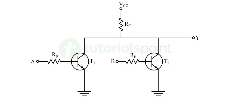
The operation of this RTL NOR gate for different input combinations is highlighted in the following table −
| Input A | Input B | Transistor T1 | Transistor T2 | Output Y |
|---|---|---|---|---|
| 0 | 0 | Off | Off | 1 |
| 0 | 1 | Off | On | 0 |
| 1 | 0 | On | Off | 0 |
| 1 | 1 | On | On | 0 |
Similarly, we can also implement other types of logic gates as well.
Advantages of RTL Family
The following are some key advantages of resistor-transistor logic family −
- Electronic circuits designed using RTL logic family are simple in design, as they consist of a minimum number of resistors and transistors.
- Circuits manufactured in RTL family are less expensive. These circuits consume less amount of power than circuits implemented in other logic families.
Disadvantages of RTL Family
The following are some major drawbacks of resistor-transistor logic families −
- RTL circuits have low noise margin. This limitation makes them susceptible to noise and interference.
- These circuits have poor fan-out.
- RTL circuits are slower in operation due to high propagation delay.
- RTL family is not suitable for designing complex circuits due to some practical limitations in terms of design scalability and performance.
Applications of RTL Family
Resistor-Transistor Logic (RTL) family finds some limited applications in the field of digital electronics. Some common applications of RTL family are listed below −
- RTL family is cost-effective and easy to understand and design. For this reason, it is widely used for educational purposes in labs and classrooms to demonstrate digital electronic concepts to students.
- RTL family is also used to design circuits for low-frequency control applications. Due to simplicity and ease of implementation, RTL family can be used for prototyping and experimental purposes.
Diode Transistor Logic (DTL)
In diode-transistor logic (DTL) family, the diodes and transistors are the key elements combinedly used to implement digital logic functions.
The following example circuit demonstrates the electronic circuit design in DTL family.
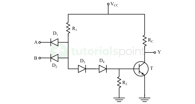
It is a two-input NAND gate. Where, A and B are inputs of the NAND gate and Y is the output of the gate.
The operation of this two-input NAND gate is explained in the following truth table −
| Input A | Input B | Diode D1 | Diode D2 | Transistor T | Output Y |
|---|---|---|---|---|---|
| 0 | 0 | Forward biased | Forward biased | Off | 1 |
| 0 | 1 | Forward biased | Reverse biased | Off | 1 |
| 1 | 0 | Reverse biased | Forward biased | Off | 1 |
| 1 | 1 | Reverse biased | Reverse biased | On | 0 |
We can also implement other types of logic circuits using the diode-transistor logic family.
Advantages of DTL Family
The following are some key advantages of diode-transistor logic family −
- DTL circuits are easy and simple to design and implement, as they consist of only diodes, transistors, and resistors.
- DTL circuits are cost-effective as they use basic electronic components like diodes and transistors which are generally cheap.
- DTL circuits have good noise immunity. Hence, these circuits are relatively less susceptible to noise and interference than some other types of logic families.
- DTL circuits have high fan-out. The power dissipation in DTL circuits is comparatively low.
Limitations of DTL Family
Apart from the advantages given above, the DTL circuits also have some disadvantages which are listed below −
- DTL family circuits require higher amount of power as compared to other logic families.
- DTL circuits consist of a greater number of elements than other types of logic families.
- DTL circuits have a moderate speed of operation. This is due to high propagation delay.
- DTL circuits are not suitable to design more complex digital circuits due to increased complexity and size of the circuit.
Applications of DTL Family
The following are some common applications of diode-transistor logic family −
- DTL family was popular in early digital computers and other digital systems.
- These days, DTL circuits are mainly used for educational purposes to explain the implementation of digital logic designs to students.
- DTL circuits are used to design custom electronic projects.
Transistor-Transistor Logic (TTL)
Transistor-Transistor Logic (TTL) is one of the most popular logic family in the field of digital electronics. In this logic family, the transistor is the key functional element which is operated as a switch to perform the logical operations.
Let us now understand how we can design a logic circuit in TTL family. The following figure shows a two-input NAND gate −
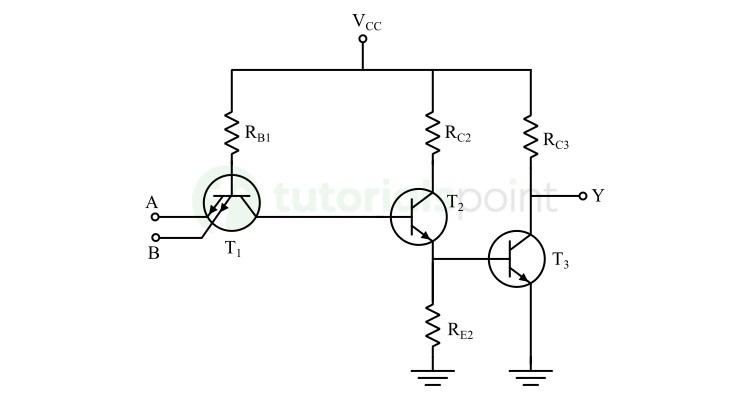
Here, A and B are the input terminals and Y is the output terminal. The operation of this circuit is summarized in the following table.
| Input A | Input B | Emitter Junction of Transistor T1 | Emitter Junction of Transistor T2 | Transistor T2 and T3 | Output Y |
|---|---|---|---|---|---|
| 0 | 0 | Forward biased | Forward biased | Off | 1 |
| 0 | 1 | Forward biased | Reverse biased | Off | 1 |
| 1 | 0 | Reverse biased | Forward biased | Off | 1 |
| 1 | 1 | Reverse biased | Reverse biased | On | 0 |
In the same manner, we can also design other logic gates in the transistor-transistor logic (TTL) family.
Advantages of TTL Family
Here are some of the key advantages of TTL family −
- TTL circuits have high speeds of operation and hence well-suited to use in high-speed digital systems.
- TTL circuits are standardized to make them compatible with a variety of digital circuits and systems.
- TTL circuits have good noise immunity. Thus, they are suitable to use in noisy environments.
Disadvantages of TTL Family
Although, TTL circuits have several advantages as listed above. But they also have some disadvantages which are given below −
- TTL circuits consume more power than other types of logic families. This limitation makes the TTL circuits less energy efficient.
- TTL circuits generate significant heat during operation and this is due to high power consumption. Thus, a proper heat management system is required.
- TTL logic levels are relatively strict, requiring specific voltage levels for proper operation. This can sometimes lead to compatibility issues with other logic families.
- TTL circuits have a significant propagation delay that limit their use in certain high-speed systems.
Applications of TTL Family
Transistor-Transistor Logic (TTL) family are widely used in various applications in the field of digital electronics. Some of the common applications of TTL family are listed below −
- TTL circuits are widely used in digital computers, memory units, CPUs, etc.
- TTL circuits are also used in embedded systems for different purposes such as interfacing with sensors, processing data in real-time applications, and more.
- In communication systems, TTL circuits are for signal conditioning, protocol handling, data processing, etc. TTL circuits are commonly used in a variety of testing and measuring instruments.
Conclusion
In conclusion, a logic family is a set of digital circuits that share same technical parameters such as logic levels, voltage levels, processing speed, etc. In this chapter, we explained the most commonly used digital logic families viz. RTL, DTL, and TTL, along with their advantages, disadvantages, and applications.
