- Digital Electronics - Home
- Digital Electronics Basics
- Types of Digital Systems
- Types of Signals
- Logic Levels And Pulse Waveforms
- Digital System Components
- Digital Logic Operations
- Digital Systems Advantages
- Number Systems
- Number Systems
- Binary Numbers Representation
- Binary Arithmetic
- Signed Binary Arithmetic
- Octal Arithmetic
- Hexadecimal Arithmetic
- Complement Arithmetic
- Base Conversions
- Base Conversions
- Binary to Decimal Conversion
- Decimal to Binary Conversion
- Binary to Octal Conversion
- Octal to Binary Conversion
- Octal to Decimal Conversion
- Decimal to Octal Conversion
- Hexadecimal to Binary Conversion
- Binary to Hexadecimal Conversion
- Hexadecimal to Decimal Conversion
- Decimal to Hexadecimal Conversion
- Octal to Hexadecimal Conversion
- Hexadecimal to Octal Conversion
- Binary Codes
- Binary Codes
- 8421 BCD Code
- Excess-3 Code
- Gray Code
- ASCII Codes
- EBCDIC Code
- Code Conversion
- Error Detection & Correction Codes
- Logic Gates
- Logic Gates
- AND Gate
- OR Gate
- NOT Gate
- Universal Gates
- XOR Gate
- XNOR Gate
- CMOS Logic Gate
- OR Gate Using Diode Resistor Logic
- AND Gate vs OR Gate
- Two Level Logic Realization
- Threshold Logic
- Boolean Algebra
- Boolean Algebra
- Laws of Boolean Algebra
- Boolean Functions
- DeMorgan's Theorem
- SOP and POS Form
- POS to Standard POS Form
- Minimization Techniques
- K-Map Minimization
- Three Variable K-Map
- Four Variable K-Map
- Five Variable K-Map
- Six Variable K-Map
- Don't Care Condition
- Quine-McCluskey Method
- Min Terms and Max Terms
- Canonical and Standard Form
- Max Term Representation
- Simplification using Boolean Algebra
- Combinational Logic Circuits
- Digital Combinational Circuits
- Digital Arithmetic Circuits
- Multiplexers
- Multiplexer Design Procedure
- Mux Universal Gate
- 2-Variable Function Using 4:1 Mux
- 3-Variable Function Using 8:1 Mux
- Demultiplexers
- Mux vs Demux
- Parity Bit Generator and Checker
- Comparators
- Encoders
- Keyboard Encoders
- Priority Encoders
- Decoders
- Arithmetic Logic Unit
- 7-Segment LED Display
- Code Converters
- Code Converters
- Binary to Decimal Converter
- Decimal to BCD Converter
- BCD to Decimal Converter
- Binary to Gray Code Converter
- Gray Code to Binary Converter
- BCD to Excess-3 Converter
- Excess-3 to BCD Converter
- Adders
- Half Adders
- Full Adders
- Serial Adders
- Parallel Adders
- Full Adder using Half Adder
- Half Adder vs Full Adder
- Full Adder with NAND Gates
- Half Adder with NAND Gates
- Binary Adder-Subtractor
- Subtractors
- Half Subtractors
- Full Subtractors
- Parallel Subtractors
- Full Subtractor using 2 Half Subtractors
- Half Subtractor using NAND Gates
- Sequential Logic Circuits
- Digital Sequential Circuits
- Clock Signal and Triggering
- Latches
- Shift Registers
- Shift Register Applications
- Binary Registers
- Bidirectional Shift Register
- Counters
- Binary Counters
- Non-binary Counter
- Design of Synchronous Counter
- Synchronous vs Asynchronous Counter
- Finite State Machines
- Algorithmic State Machines
- Flip Flops
- Flip-Flops
- Conversion of Flip-Flops
- D Flip-Flops
- JK Flip-Flops
- T Flip-Flops
- SR Flip-Flops
- Clocked SR Flip-Flop
- Unclocked SR Flip-Flop
- Clocked JK Flip-Flop
- JK to T Flip-Flop
- SR to JK Flip-Flop
- Triggering Methods:Flip-Flop
- Edge-Triggered Flip-Flop
- Master-Slave JK Flip-Flop
- Race-around Condition
- A/D and D/A Converters
- Analog-to-Digital Converter
- Digital-to-Analog Converter
- DAC and ADC ICs
- Realization of Logic Gates
- NOT Gate from NAND Gate
- OR Gate from NAND Gate
- AND Gate from NAND Gate
- NOR Gate from NAND Gate
- XOR Gate from NAND Gate
- XNOR Gate from NAND Gate
- NOT Gate from NOR Gate
- OR Gate from NOR Gate
- AND Gate from NOR Gate
- NAND Gate from NOR Gate
- XOR Gate from NOR Gate
- XNOR Gate from NOR Gate
- NAND/NOR Gate using CMOS
- Full Subtractor using NAND Gate
- AND Gate Using 2:1 MUX
- OR Gate Using 2:1 MUX
- NOT Gate Using 2:1 MUX
- Memory Devices
- Memory Devices
- RAM and ROM
- Cache Memory Design
- Programmable Logic Devices
- Programmable Logic Devices
- Programmable Logic Array
- Programmable Array Logic
- Field Programmable Gate Arrays
- Digital Electronics Families
- Digital Electronics Families
- CPU Architecture
- CPU Architecture
Logic Levels and Pulse Waveforms
A digital system is a type of electronic system that utilizes the binary number system to work. In other words, a digital system is a two-state electronic system used to represent two binary digits 0 and 1, where 0 represents the low or "off" state and 1 represents the high or "on" state of the system.
In the field of digital electronics, different voltage levels are used to represent the two binary values, i.e., 0 and 1 in a digital signal. These voltage levels are known as logic levels.
In this chapter, we will learn the concept of logic levels and pulse waveforms.
What is a Logic Level?
In digital electronics, a voltage level that represents a specific binary value either 0 or 1 is called a logic level. Here, the binary value 0 represents the low voltage level while the binary value 1 represents the high value level.
Hence, the logic levels can be classified into the following two types −
- High Logic Level
- Low Logic Level
Lets discuss these two logic levels in detail.
High Logic Level
In the case of a digital system, the voltage level closer to the maximum voltage level that the system can handle without getting damaged is called high logic level.
The high logic level is represented by the binary digit "1". The voltage level for a high logic level depends on the technological standard used to design the system. Typically, the voltage value between 2 V and 5 V represents the high logic level or 1.
Low Logic Level
In a digital system, the low logic level is defined as the maximum voltage level for which the system will remain in the OFF state.
The low logic level is represented by the binary digit "0". Similar to the high logic level, the voltage level for a low logic level depends on the technology standard used to design the system. In actual practice, the voltage value between 0 V and 0.8 V represents the low logic level or logic 0.
In most practical digital system, the ground voltage is used to represent the low logic level.
Note − The voltage range between the voltage values 0.8 V and 2 V is known as the indeterminate logic range. If a digital signal lies between the value 0.8 and 2 V, the response of the system is not predictable.
What is a Pulse?
A pulse is a type of an electronic signal that can change suddenly between two possible states i.e., high state and low state.
The graph used to represent the transition of a pulse is called the pulse waveform. Pulses are very important in the operation of digital systems, communication systems, and many other electronics devices and circuits.
Depending on the switching characteristics, the pulses can be classified into the following two types −
- Positive Pulse − When a signal normally goes from low logic level to the high logic level and then returns to its normal low logic level, then it is called a positive pulse.
- Negative Pulse − When a signal normally goes from high logic level to the low logic level and then returns to its normal high logic level, then it is known as a negative pulse.
The pulse waveforms for positive and negative pulses are depicted in the following figure.
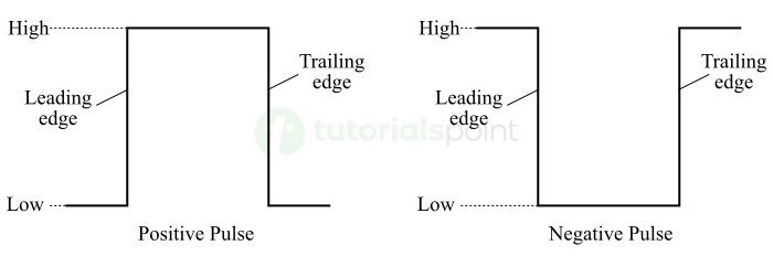
A pulse has two edges namely, a leading edge and a trailing edge.
In the case of a positive pulse, the edge going from low logic level to high logic level is called the leading edge, and the edge going from high logic level to low logic level is called the trailing edge.
In the case of a negative pulse, the edge going from high logic level to low logic level is called the leading edge, whereas the edge going from low logic level to high logic level is called the trailing edge.
The positive and negative pulse waveforms shown in the above figure are ideal pulse waveforms, because their leading and trailing edges change instantaneously i.e., in zero time. But in actual practice, the edges of pulses do not change instantaneously from low logic level to high logic level or from high logic level to low logic level.
The pulse waveforms that take a finite time to change from low logic level to high logic level and vice-versa are known as non-ideal pulse waveforms.
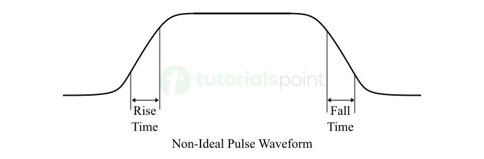
In the case of a non-ideal pulse waveform, the time taken by the pulse to go from low logic level to high logic level is called the rise time. The time taken by the pulse to go from the high logic level to the low logic level is called the fall time.
Types of Pulse Waveforms
The pulse waveforms used in digital systems are mainly classified into the following two types −
Periodic Waveforms
A pulse waveform that repeats itself at regular intervals of time is called a periodic waveform. The time taken to complete one cycle is called the time period of the periodic waveform.
Non-periodic Waveforms
A pulse waveform which does not repeat itself at regular intervals of time is termed as a non-periodic or aperiodic waveform.
Conclusion
In conclusion, "logic level" is a concept used in digital systems to represent the state of the system. There are two possible logic levels in the case of digital systems namely, high logic level and low logic level. The high logic level is represented by the binary 1 while the low logic level is represented by the binary 0.
The graphical representation of a digital signal or a pulse is termed as the "pulse waveform". Pulse waveforms are used to represent the transition of a pulse or digital signal or the states of a digital system. In this chapter, we have discussed the concept of logic levels and pulse waveforms. In the next chapter, we will learn about "components of a digital system".
