- Digital Electronics - Home
- Digital Electronics Basics
- Types of Digital Systems
- Types of Signals
- Logic Levels And Pulse Waveforms
- Digital System Components
- Digital Logic Operations
- Digital Systems Advantages
- Number Systems
- Number Systems
- Binary Numbers Representation
- Binary Arithmetic
- Signed Binary Arithmetic
- Octal Arithmetic
- Hexadecimal Arithmetic
- Complement Arithmetic
- Base Conversions
- Base Conversions
- Binary to Decimal Conversion
- Decimal to Binary Conversion
- Binary to Octal Conversion
- Octal to Binary Conversion
- Octal to Decimal Conversion
- Decimal to Octal Conversion
- Hexadecimal to Binary Conversion
- Binary to Hexadecimal Conversion
- Hexadecimal to Decimal Conversion
- Decimal to Hexadecimal Conversion
- Octal to Hexadecimal Conversion
- Hexadecimal to Octal Conversion
- Binary Codes
- Binary Codes
- 8421 BCD Code
- Excess-3 Code
- Gray Code
- ASCII Codes
- EBCDIC Code
- Code Conversion
- Error Detection & Correction Codes
- Logic Gates
- Logic Gates
- AND Gate
- OR Gate
- NOT Gate
- Universal Gates
- XOR Gate
- XNOR Gate
- CMOS Logic Gate
- OR Gate Using Diode Resistor Logic
- AND Gate vs OR Gate
- Two Level Logic Realization
- Threshold Logic
- Boolean Algebra
- Boolean Algebra
- Laws of Boolean Algebra
- Boolean Functions
- DeMorgan's Theorem
- SOP and POS Form
- POS to Standard POS Form
- Minimization Techniques
- K-Map Minimization
- Three Variable K-Map
- Four Variable K-Map
- Five Variable K-Map
- Six Variable K-Map
- Don't Care Condition
- Quine-McCluskey Method
- Min Terms and Max Terms
- Canonical and Standard Form
- Max Term Representation
- Simplification using Boolean Algebra
- Combinational Logic Circuits
- Digital Combinational Circuits
- Digital Arithmetic Circuits
- Multiplexers
- Multiplexer Design Procedure
- Mux Universal Gate
- 2-Variable Function Using 4:1 Mux
- 3-Variable Function Using 8:1 Mux
- Demultiplexers
- Mux vs Demux
- Parity Bit Generator and Checker
- Comparators
- Encoders
- Keyboard Encoders
- Priority Encoders
- Decoders
- Arithmetic Logic Unit
- 7-Segment LED Display
- Code Converters
- Code Converters
- Binary to Decimal Converter
- Decimal to BCD Converter
- BCD to Decimal Converter
- Binary to Gray Code Converter
- Gray Code to Binary Converter
- BCD to Excess-3 Converter
- Excess-3 to BCD Converter
- Adders
- Half Adders
- Full Adders
- Serial Adders
- Parallel Adders
- Full Adder using Half Adder
- Half Adder vs Full Adder
- Full Adder with NAND Gates
- Half Adder with NAND Gates
- Binary Adder-Subtractor
- Subtractors
- Half Subtractors
- Full Subtractors
- Parallel Subtractors
- Full Subtractor using 2 Half Subtractors
- Half Subtractor using NAND Gates
- Sequential Logic Circuits
- Digital Sequential Circuits
- Clock Signal and Triggering
- Latches
- Shift Registers
- Shift Register Applications
- Binary Registers
- Bidirectional Shift Register
- Counters
- Binary Counters
- Non-binary Counter
- Design of Synchronous Counter
- Synchronous vs Asynchronous Counter
- Finite State Machines
- Algorithmic State Machines
- Flip Flops
- Flip-Flops
- Conversion of Flip-Flops
- D Flip-Flops
- JK Flip-Flops
- T Flip-Flops
- SR Flip-Flops
- Clocked SR Flip-Flop
- Unclocked SR Flip-Flop
- Clocked JK Flip-Flop
- JK to T Flip-Flop
- SR to JK Flip-Flop
- Triggering Methods:Flip-Flop
- Edge-Triggered Flip-Flop
- Master-Slave JK Flip-Flop
- Race-around Condition
- A/D and D/A Converters
- Analog-to-Digital Converter
- Digital-to-Analog Converter
- DAC and ADC ICs
- Realization of Logic Gates
- NOT Gate from NAND Gate
- OR Gate from NAND Gate
- AND Gate from NAND Gate
- NOR Gate from NAND Gate
- XOR Gate from NAND Gate
- XNOR Gate from NAND Gate
- NOT Gate from NOR Gate
- OR Gate from NOR Gate
- AND Gate from NOR Gate
- NAND Gate from NOR Gate
- XOR Gate from NOR Gate
- XNOR Gate from NOR Gate
- NAND/NOR Gate using CMOS
- Full Subtractor using NAND Gate
- AND Gate Using 2:1 MUX
- OR Gate Using 2:1 MUX
- NOT Gate Using 2:1 MUX
- Memory Devices
- Memory Devices
- RAM and ROM
- Cache Memory Design
- Programmable Logic Devices
- Programmable Logic Devices
- Programmable Logic Array
- Programmable Array Logic
- Field Programmable Gate Arrays
- Digital Electronics Families
- Digital Electronics Families
- CPU Architecture
- CPU Architecture
Binary Adder-Subtractor
A binary adder-subtractor is a digital circuit that is used to perform two basic arithmetic operations namely, binary addition and binary subtraction. It is an important component in various digital systems like computers, calculators, etc.
The most significant advantage of using a binary adder-subtractor is that it combines the addition and subtraction operations in a single circuit which results in compact size and lower cost.
Read this chapter to understand the circuit and operation of a binary adder-subtractor.
What is a Binary Adder-Subtractor?
In digital electronics, there is a digital circuit which employed for performing addition and subtraction operations, it is called a binary adder-subtractor.
A binary adder-subtractor is a specially designed digital arithmetic circuit that combines the functionality of addition and subtraction of binary numbers in a single circuit.
A binary adder-subtractor circuit performs the binary addition and subtraction operations on two binary numbers by following the rules given below.
Rules of Binary Addition
The following rules are to be followed while performing binary addition −
| First Bit (A) | Second Bit (B) | Sum (A + B) | Carry |
|---|---|---|---|
| 0 | 0 | 0 | 0 |
| 0 | 1 | 1 | 0 |
| 1 | 0 | 1 | 0 |
| 1 | 1 | 0 | 1 |
Rules of Binary Subtraction
The following table shows the rules to be followed while performing binary subtraction −
| First Bit (A) | Second Bit (B) | Sum (A - B) | Borrow |
|---|---|---|---|
| 0 | 0 | 0 | 0 |
| 0 | 1 | 1 | 1 |
| 1 | 0 | 1 | 0 |
| 1 | 1 | 0 | 0 |
This is all about a basic introduction to binary adder-subtractor and the rules of binary addition and subtraction. Let us now understand the circuit construction of binary adder-subtractor.
Binary Adder-Subtractor Circuit
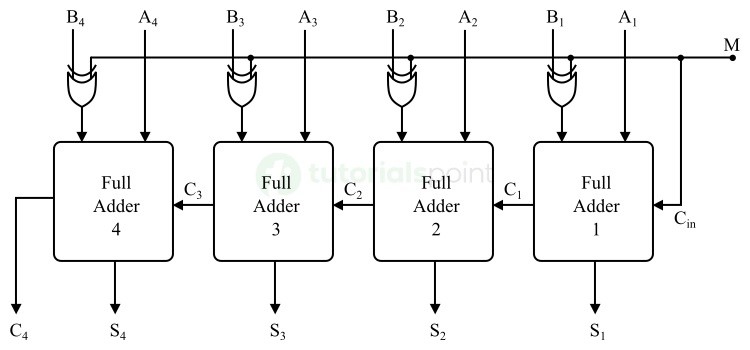
The logic circuit of a binary adder-subtractor consists of several full-adder circuits connected together. It also consists of a control circuit consisting of XOR gates and performs the mode selection function i.e., the control circuit is used to switch the circuit operation between addition and subtraction.
The circuit diagram of a binary adder-subtractor which can perform the addition or subtraction of two 4-bit binary numbers (say A and B) is shown below −
Components of a Binary Adder-Subtractor
The circuit of a binary adder-subtractor consists of the following main components −
Full Adders
A full adder is a binary arithmetic circuit used to perform the addition of three binary bits at a time. It produces two outputs namely a sum and a carry. In a binary adder-subtractor circuit, the full adder circuit can also perform the subtraction operation using the complement mechanism.
Control Circuit
It is a logic circuit used for mode selection i.e., addition mode or subtraction mode. The control circuit of a binary adder-subtractor is designed using XOR gates.
Working of Binary Adder-Subtractor
Let us now understand the operation of a binary adder-subtractor circuit shown in the above figure.
The circuit shown in the above figure is a 4-bit binary adder-subtractor. Therefore, it can perform addition or subtraction of two 4-bit binary numbers, say A and B.
In this circuit, the input M is called the mode input. It controls the operation of the circuit as described below −
- When M = 0, the circuit operates as a binary adder. Under this mode, we get $\mathrm{B_{X} \: \oplus \: 0 \: = \: B_{X}}$. Thus, each full adder receives the inputs Ax and Bx and performs their addition, i.e., Ax + Bx.
- When M = 1, the circuit operates as a binary subtractor. In this case, we get $\mathrm{B_{X} \: \oplus \: 1 \: = \: B_{X}}$ and the input carry Cin = 1. Under this mode, the full adders receive Bx inputs in their complemented form and a 1 is added through the input carry Cin. Hence, the final output of the circuit is Ax + 2s complement of Bx which is the subtraction of Ax and Bx.
This is how the binary adder-subtractor circuit performs both binary addition and binary subtraction operations.
We can conclude the working of a binary adder-subtractor in the following points −
- First of all, select the mode of operation (addition or subtraction) of the circuit. To perform binary addition, set M = 0, and to perform binary subtraction, set M = 1.
- Supply the two input binary numbers to be added or subtracted.
- The circuit will perform the addition or subtraction of input numbers depending on the selected mode and produce a result (either a sum or a difference).
Advantages of Binary Adder-Subtractor
In the field of digital circuit design, it is important to make the circuit compact as much as possible. Since a binary adder-subtractor circuit combines both binary addition and subtraction operations in a single circuit. It results in the following key advantages −
- Reduced circuit complexity
- Compact and simpler system design
- Versatility
- Ability to perform fast and efficient arithmetic operations
- Reduced need for hardware components
- Compatibility with a wide range of digital systems and devices
- Low power consumption, etc.
Limitations of Binary Adder-Subtractor
Binary adder-subtractor has several advantages as listed above. But it also has some disadvantages and limitations.
Some of the key limitations of binary adder-subtractor are listed below −
- A binary adder-subtractor requires more advanced circuit components and algorithms to achieve high precision and accuracy in addition and subtraction operations.
- The functionality of a binary adder-subtractor is limited to addition and subtraction operations only. It requires additional circuitry and algorithms to implement other mathematical operations like multiplication and division.
- The circuit complexity of a binary adder-subtractor is increased significantly when it is designed to perform addition and subtraction of large numbers of bits and floating-point numbers.
- When the number of digits increases in the numbers to be added or subtracted, the circuit becomes slower due to propagation delay.
- A binary adder-subtractor has a limited dynamic range due to which overflow or underflow conditions can occur when dealing with very large or very small numbers respectively.
- Since a binary adder-subtractor uses 2s complement arithmetic to perform binary subtraction. To implement this operation, we require an additional logic circuit which increases the overall complexity of the circuit.
While designing a binary adder-subtractor, we have to take care of all these limitations to ensure higher efficiency and better performance of the circuit.
Applications of Binary Adder-Subtractor
In digital electronics, the binary adder-subtractor finds applications in a variety of digital systems and electronic devices. Some common devices are listed below in which the binary adder-subtractor is used as a crucial component −
- Arithmetic Logic Units − To perform arithmetic and logical operations.
- Microprocessors and Microcontrollers − To perform mathematical computations.
- Communication Systems − To process digital signals and filter operations on binary data.
- Calculators − To perform addition and subtraction operations.
- Control Systems − To perform real-time signal processing and produce feedback and other control signals.
Conclusion
In this chapter, we explained the basic theory and working of binary adder-subtractor. A binary adder-subtractor is a digital electronic circuit that can perform both addition and subtraction of binary numbers. It combines two arithmetic operations (addition and subtraction) into a single circuit and hence reduces the circuit complexity and size of the digital system.
Binary adder-subtractor are widely used in various digital systems and devices such as microprocessors, microcontrollers, calculators, and more.
