- Digital Electronics - Home
- Digital Electronics Basics
- Types of Digital Systems
- Types of Signals
- Logic Levels And Pulse Waveforms
- Digital System Components
- Digital Logic Operations
- Digital Systems Advantages
- Number Systems
- Number Systems
- Binary Numbers Representation
- Binary Arithmetic
- Signed Binary Arithmetic
- Octal Arithmetic
- Hexadecimal Arithmetic
- Complement Arithmetic
- Base Conversions
- Base Conversions
- Binary to Decimal Conversion
- Decimal to Binary Conversion
- Binary to Octal Conversion
- Octal to Binary Conversion
- Octal to Decimal Conversion
- Decimal to Octal Conversion
- Hexadecimal to Binary Conversion
- Binary to Hexadecimal Conversion
- Hexadecimal to Decimal Conversion
- Decimal to Hexadecimal Conversion
- Octal to Hexadecimal Conversion
- Hexadecimal to Octal Conversion
- Binary Codes
- Binary Codes
- 8421 BCD Code
- Excess-3 Code
- Gray Code
- ASCII Codes
- EBCDIC Code
- Code Conversion
- Error Detection & Correction Codes
- Logic Gates
- Logic Gates
- AND Gate
- OR Gate
- NOT Gate
- Universal Gates
- XOR Gate
- XNOR Gate
- CMOS Logic Gate
- OR Gate Using Diode Resistor Logic
- AND Gate vs OR Gate
- Two Level Logic Realization
- Threshold Logic
- Boolean Algebra
- Boolean Algebra
- Laws of Boolean Algebra
- Boolean Functions
- DeMorgan's Theorem
- SOP and POS Form
- POS to Standard POS Form
- Minimization Techniques
- K-Map Minimization
- Three Variable K-Map
- Four Variable K-Map
- Five Variable K-Map
- Six Variable K-Map
- Don't Care Condition
- Quine-McCluskey Method
- Min Terms and Max Terms
- Canonical and Standard Form
- Max Term Representation
- Simplification using Boolean Algebra
- Combinational Logic Circuits
- Digital Combinational Circuits
- Digital Arithmetic Circuits
- Multiplexers
- Multiplexer Design Procedure
- Mux Universal Gate
- 2-Variable Function Using 4:1 Mux
- 3-Variable Function Using 8:1 Mux
- Demultiplexers
- Mux vs Demux
- Parity Bit Generator and Checker
- Comparators
- Encoders
- Keyboard Encoders
- Priority Encoders
- Decoders
- Arithmetic Logic Unit
- 7-Segment LED Display
- Code Converters
- Code Converters
- Binary to Decimal Converter
- Decimal to BCD Converter
- BCD to Decimal Converter
- Binary to Gray Code Converter
- Gray Code to Binary Converter
- BCD to Excess-3 Converter
- Excess-3 to BCD Converter
- Adders
- Half Adders
- Full Adders
- Serial Adders
- Parallel Adders
- Full Adder using Half Adder
- Half Adder vs Full Adder
- Full Adder with NAND Gates
- Half Adder with NAND Gates
- Binary Adder-Subtractor
- Subtractors
- Half Subtractors
- Full Subtractors
- Parallel Subtractors
- Full Subtractor using 2 Half Subtractors
- Half Subtractor using NAND Gates
- Sequential Logic Circuits
- Digital Sequential Circuits
- Clock Signal and Triggering
- Latches
- Shift Registers
- Shift Register Applications
- Binary Registers
- Bidirectional Shift Register
- Counters
- Binary Counters
- Non-binary Counter
- Design of Synchronous Counter
- Synchronous vs Asynchronous Counter
- Finite State Machines
- Algorithmic State Machines
- Flip Flops
- Flip-Flops
- Conversion of Flip-Flops
- D Flip-Flops
- JK Flip-Flops
- T Flip-Flops
- SR Flip-Flops
- Clocked SR Flip-Flop
- Unclocked SR Flip-Flop
- Clocked JK Flip-Flop
- JK to T Flip-Flop
- SR to JK Flip-Flop
- Triggering Methods:Flip-Flop
- Edge-Triggered Flip-Flop
- Master-Slave JK Flip-Flop
- Race-around Condition
- A/D and D/A Converters
- Analog-to-Digital Converter
- Digital-to-Analog Converter
- DAC and ADC ICs
- Realization of Logic Gates
- NOT Gate from NAND Gate
- OR Gate from NAND Gate
- AND Gate from NAND Gate
- NOR Gate from NAND Gate
- XOR Gate from NAND Gate
- XNOR Gate from NAND Gate
- NOT Gate from NOR Gate
- OR Gate from NOR Gate
- AND Gate from NOR Gate
- NAND Gate from NOR Gate
- XOR Gate from NOR Gate
- XNOR Gate from NOR Gate
- NAND/NOR Gate using CMOS
- Full Subtractor using NAND Gate
- AND Gate Using 2:1 MUX
- OR Gate Using 2:1 MUX
- NOT Gate Using 2:1 MUX
- Memory Devices
- Memory Devices
- RAM and ROM
- Cache Memory Design
- Programmable Logic Devices
- Programmable Logic Devices
- Programmable Logic Array
- Programmable Array Logic
- Field Programmable Gate Arrays
- Digital Electronics Families
- Digital Electronics Families
- CPU Architecture
- CPU Architecture
Digital Electronics - Half Subtractor
In digital electronics, a subtractor is a combinational logic circuit that can perform the subtraction of two number (binary numbers) and produce the difference between them. It is a combinational circuit that means its output depends on its present inputs only. Although, in practice, the subtraction of two binary number is accomplished by taking the 1's or 2's compliment of the subtrahend and adding it to the minuend.
In this way, the subtraction operation of binary numbers can be converted into simple addition operation which makes hardware construction simple and less expensive. There are two types of subtractors namely, Half Subtractor and Full Subtractor.
In this article, we will discuss the half subtractor, its basic definition, circuit diagram, truth table, characteristic equation, etc. So let's begin with the basic definition of half subtractor.
What is a Half-Subtractor?
A half-subtractor is a combinational logic circuit that have two inputs and two outputs (i.e. difference and borrow). The half subtractor produces the difference between the two binary bits at the input and also produces a borrow output (if any). In the subtraction (A-B), A is called as Minuend bit and B is called as Subtrahend bit. The block diagram and logic circuit diagram of the half subtractor is shown in Figure-1.
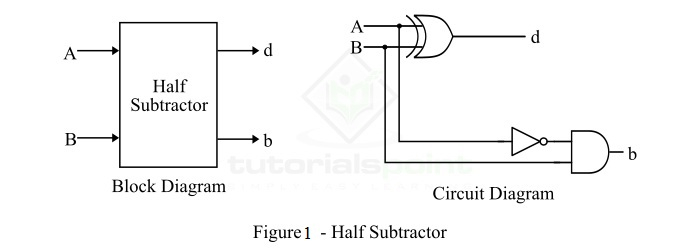
Hence, from the logic circuit diagram, it is clear that a half subtractor can be realized using an XOR gate together with a NOT gate and an AND gate.
In the half subtractor as shown in figure-1, A and B are the inputs, d and b are the outputs. Where, d indicates the difference and b indicates the borrow output. The borrow output (b) is the signal that tells the next stage that a 1 has been borrowed.
Operation of Half Subtractor
Now, let us understand the operation of the half subtractor circuit. Half subtractor performs its operation to find the difference of two binary digits according to the rules of binary subtraction, which are as follows −
The output borrow of b is zero (0) as long as the minuend bit (A) is greater than or equal to the subtrahend bit (B), i.e. A B. The output borrow is a 1 when A = 0 and B = 1.
From the logic circuit diagram of the half subtractor, it is clear that the difference bit (d) is obtained by the XOR operation of the two inputs A and B, and the borrow bit is obtained by AND operation of the compliment of the minuend (A') with the subtrahend (B).
Truth Table of Half Subtractor
The following is the truth table the half-subtractor −
| Inputs | Outputs | ||
|---|---|---|---|
| A | B | D (Difference) | B (Borrow) |
| 0 | 0 | 0 | 0 |
| 0 | 1 | 1 | 1 |
| 1 | 0 | 1 | 0 |
| 1 | 1 | 0 | 0 |
K-Map for Half Subtractor
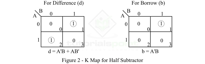
We can use the K-Map (or Karnaugh Map), a method for simplifying Boolean algebra, to determine equations of the difference bit (d) and the output borrow (b).
The K-Map simplification for half subtractor is shown in Figure-2.
Characteristic Equation of Half Subtractor
The characteristic equations of the half subtractor, i.e. equations of the difference bit (d) and the output borrow bit (b) are obtained by following the rules of binary subtraction. These equations are given as follows −
The difference bit (d) of the half subtractor is given by XORing the two inputs A and B. Therefore,
$$\mathrm{Difference, \: d \: = \: A \oplus B \: = \: A'B \: + \: AB'}$$
The borrow (b) of the half subtractor is the AND of A (compliment of A) and B. Therefore,
$$\mathrm{Borrow, \: b \: = \: A'B}$$
Applications of Half Subtractor
The following are some important applications of half subtractor −
- Half subtractor is used in ALU (Arithmetic Logic Unit) of processors.
- Half subtractor can also be used in amplifiers to compensate the sound distortion.
- It is also used to decrease the force of radio signals or audio signals.
- Half subtractor is also used to increase or decrease operators.
Conclusion
From the above discussion, we can conclude that a half subtractor is a combinational logic circuit that can calculate the difference of two binary digits. A half subtractor can only be used to subtract the LSB (Least Significant Bit) of the subtrahend from the LSB of the minuend when one binary number is subtracted from another binary number.
