
- Semiconductor Devices - Home
- Introduction
- Atomic Combinations
- Conduction in Solid Materials
- Conductivity & Mobility
- Types of Semiconductor
- Doping in Semiconductors
- Junction Diodes
- Depletion Zone
- Barrier Potential
- Junction Biasing
- Leakage Current
- Diode Characteristics
- Light Emitting Diode
- Zener Diode
- Photo Diode
- Photovoltaic Cells
- Varactor Diode
- Bipolar Transistors
- Construction of a Transistor
- Transistor Biasing
- Configuration of Transistors
- Field Effect Transistors
- JFET Biasing
- Semiconductor Devices - MOSFET
- Operational Amplifiers
- Practical Op-Amps
- Semiconductor Devices - Integrator
- Differentiator
- Oscillators
- Feedback & Compensation
- Semiconductor Devices - Quick Guide
- Semiconductor Devices - Resources
- Semiconductor Devices - Discussion
Operational Amplifiers
An operational amplifier, or op-amp, is a very high gain differential amplifier with high input impedance and low output impedance. Operational amplifiers are typically used to provide voltage amplitude changes, oscillators, filter circuits, etc. An op-amp may contain a number of differential amplifier stages to achieve a very high voltage gain.
This is a high gain differential amplifier using direct coupling between the output and the input. This is suitable for DC as well as AC operations. Operational amplifiers perform numerous electronic functions such as instrumentation devices, signal generators, active filters, etc. besides various mathematical operations. This versatile device is also used in many nonlinear applications, such as voltage comparators, Analogtodigital converters and DigitaltoAnalog converters, Logarithmic amplifiers, nonlinear function generators, etc.
Basic Differential Amplifier
The following illustration shows a basic differential amplifier −
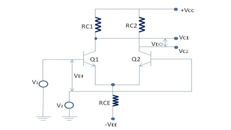
In the above figure −
VDI = differential input
VDI = V1 V2
VDO = differential output
VDO = VC1 - VC2
This amplifier amplifies the difference between the two input signals, V1 and V2.
Differential voltage gain,
$$A_d = \frac{V_{DO}}{V_{DI}}$$
and
$$A_d = \frac{(V_{C1} - V_{C2})}{V_{DI}}$$
As shown in the following figure, basic operational amplifier consists of three stages −
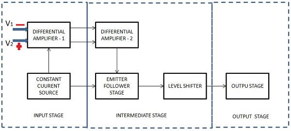
Input Stage
This is the first stage and has the following characteristics.
- High CMR (Common Mode Rejection)
- High input impedance
- Wide band width
- Low (DC) input offset
These are some significant characteristics for the performance of the operational amplifier. This stage consists of a differential amplifier stage and a transistor is biased so that it acts as a constant current source. The constant current source greatly increases the CMR of the differential amplifier.
Following are the two inputs to the differential amplifier −
- V1 = Non inverting input
- V2 = Inverting input
Intermediate Stage
This is the second stage and designed to get better voltage and current gains. The current gain is required to supply sufficient current to drive the output stage, where most of the operational amplifier power is generated. This stage consists of one or more differential amplifiers followed by an emitter follower and a DC level shifting stage. Level shifting circuit enables an amplifier to have two differential inputs with a single output.
| Vout = +ve | when V1 > V2 |
| Vout = -ve | when V2 < V1 |
| Vout = 0 | when V1 = V2 |
Output Stage
This is the last stage of the op-amp and is designed to have low output impedance. This provides the needed current to drive the load. More or less current will be drawn from the output stage as and when the load varies. Therefore, it is essential that the previous stage operates without being influenced by the output load. This requirement is met by designing this stage so as to have high input impedance and high current gain, however with low output impedance.
The operational amplifier has two inputs: Non-inverting input and Inverting input.
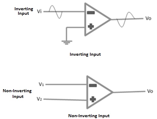
The above figure shows inverting type of operational amplifier. A signal which is applied at the inverting input terminal is amplified however the output signal is out of phase with the input signal by 180 degrees. A signal applied at the noninverting input terminal is amplified and the output signal is in phase with the input signal.
The op-amp can be connected in large number of circuits to provide various operating characteristics.