- Home
- Brief Overview of IoT
- Introduction to ESP32
- Installing the ESP32 Board in Arduino IDE
- Setting up RTOS for dual-core and multi-threaded operation
- Interfacing ESP32 with MPU6050
- Interfacing ESP32 with Analog sensors
- ESP32 Preferences
- ESP32 SPIFFS storage (A mini-SD Card in the chip itself)
- Interfacing OLED Display with ESP32
- WiFi on ESP32
- Transmitting data over WiFi using HTTP
- Transmitting data over WiFi using HTTPS
- Transmitting data over WiFi using MQTT
- Transmitting data over Bluetooth
- Getting current time using NTP Client
- Performing the (OTA) update of ESP32 firmware
- Applications of ESP32
- Next steps for you as a developer
- ESP32 for IoT Useful Resources
- Quick Guide
- Useful Resources
- Discussion
Interfacing ESP32 with MPU6050
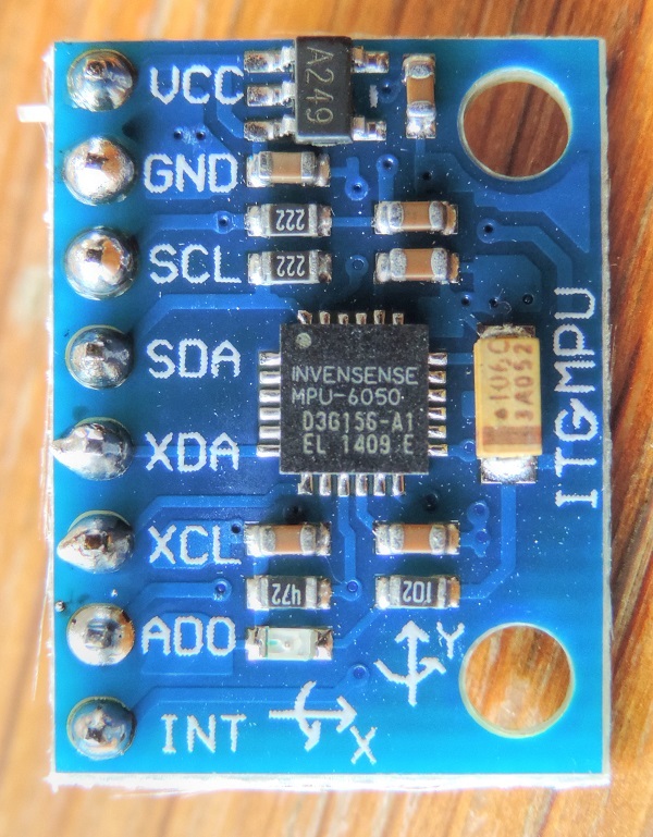
Accelerometers and Gyroscopes are widely used in Industrial IoT for measuring the health and operating parameters of various machines. MPU6050 is a popular six-axis accelerometer + gyroscope. It is a MEMS (Micro-Electro-Mechanical Systems) sensor, meaning it is very compact (as can be seen from the image below) and, for a wide range of frequencies, very accurate as well.
In this tutorial, we will see how to interface ESP32 with the MPU6050. In the process, you will learn about the usage of the I2C (Inter-Integrated Circuit) protocol, which will then enable you to interface the ESP32 with several sensors and peripherals which communicate using the I2C protocol. You will need your ESP32, an MPU6050, and a couple of jumper wires for this tutorial.
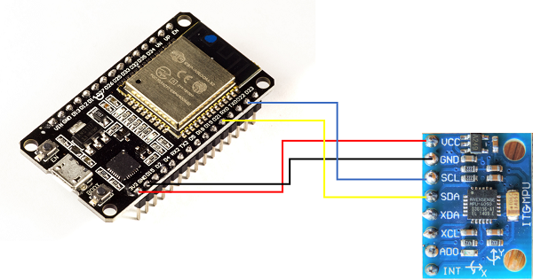
Connecting MPU6050 with ESP32
As shown in the image below, you need to connect the SDA line of MPU6050 to pin 21 on ESP32, SCL line to pin 22, GND to GND, and VCC to 3V3 pin. The other pins of MPU6050 need not be connected.
Code Walkthrough
GitHub Link − https://github.com/
ESP32, and Arduino in general refer to the I2C protocol as 'Wire'. Therefore the required library import is Wire.h
#include<Wire.h>
Next we define constants and global variables.
const int MPU_ADDR = 0x68; // I2C address of the MPU-6050
int16_t AcX, AcY, AcZ, Tmp, GyX, GyY, GyZ;
Every I2C device has a fixed address using which other devices identify it and communicate with it. For MPU6050, that address is 0x68. We will use it later when initializing the I2C communication with the MPU6050. We next move to the setup code.
void setup() {
   Serial.begin(115200);
   Wire.begin(21, 22, 100000); // sda, scl, clock speed
   Wire.beginTransmission(MPU_ADDR);
   Wire.write(0x6B);  // PWR_MGMT_1 register
   Wire.write(0);     // set to zero (wakes up the MPU−6050)
   Wire.endTransmission(true);
   Serial.println("Setup complete");
}
The first line is trivial. We are initiating communication with the serial monitor at 115200 baud rate. Next, we begin the I2C communication. For that, we provide 3 arguments to the Wire.begin() function.
These are the SDA and SCL pins and the clock speed. Now, I2C communication requires two lines: the Data line (SDA) and the Clock line (SCL). On ESP32, pins 21 and 22 are generally reserved for I2C, with 21 being SDA and 22 being SCL. For communicating with MPU6050, we have two speed options: 100kbit/s and 400kbit/s. We have chosen 100kHz here. You can choose the higher speed option as well if your use-case requires it.
Next, we indicate to the ESP32 that we want to communicate with the chip which has the address equal to MPU_ADDR, using the Wire.beginTransmission() command. At this point, you would have guessed that one ESP32 chip can communicate with multiple I2C peripherals. In fact, there are 128 unique addresses possible (address field is 7 bits long), and so the ESP32 can communicate with 128 different peripherals using I2C, provided all of them have different addresses.
In the next couple of lines, we are setting the PWR_MGMT_1 register of MPU6050 to 0. This is used to wake up the MPU6050. The address 0x6B of the PWR_MGMT_1 register is the address within MPU6050's memory.
It has nothing to do with the I2C address of MPU6050. Once the MPU is woken up, we end this particular transmission over I2C and our setup is complete, and we indicate that on the Serial Monitor using a print statement. Now let's jump into the loop. You will notice that we pass a boolean true as an argument to Wire.endTransmission. This tells the ESP32 to send a stop command and release the I2C lines. If we replace true with false, the ESP32 will send a restart instead of stop, keeping the connection active.
void loop() {
   Wire.beginTransmission(MPU_ADDR);
   Wire.write(0x3B);  // starting with register 0x3B (ACCEL_XOUT_H)
   Wire.endTransmission(true);
   Wire.beginTransmission(MPU_ADDR);
   Wire.requestFrom(MPU_ADDR, 14, true); // request a total of 14 registers
   AcX = Wire.read() −− 8 | Wire.read(); // 0x3B (ACCEL_XOUT_H) & 0x3C (ACCEL_XOUT_L)
   AcY = Wire.read() −− 8 | Wire.read(); // 0x3D (ACCEL_YOUT_H) & 0x3E (ACCEL_YOUT_L)
   AcZ = Wire.read() −− 8 | Wire.read(); // 0x3F (ACCEL_ZOUT_H) & 0x40 (ACCEL_ZOUT_L)
   Tmp = Wire.read() −− 8 | Wire.read(); // 0x41 (TEMP_OUT_H) &  0x42 (TEMP_OUT_L)
   GyX = Wire.read() −− 8 | Wire.read(); // 0x3B (ACCEL_XOUT_H) & 0x3C (ACCEL_XOUT_L)
   GyY = Wire.read() −− 8 | Wire.read(); // 0x3D (ACCEL_YOUT_H) & 0x3E (ACCEL_YOUT_L)
   GyZ = Wire.read() −− 8 | Wire.read(); // 0x3F (ACCEL_ZOUT_H) & 0x40 (ACCEL_ZOUT_L)


   Serial.print(AcX); Serial.print(" , ");
   Serial.print(AcY); Serial.print(" , ");
   Serial.print(AcZ); Serial.print(" , ");
   Serial.print(GyX); Serial.print(" , ");
   Serial.print(GyY); Serial.print(" , ");
   Serial.print(GyZ); Serial.print("\n");
}
In the loop, if you scan through the above code snippet, you will see that we perform a total of two transmissions. In the first one, we indicate to the MPU6050 the address from which we would like to start reading the data, or rather set the MPU6050's internal pointer to this particular address. In the second transmission, we tell the MPU that we request 14 bytes starting from the address sent earlier. Then we read the bytes one by one. You may notice that we don't have a Wire.endTransmission(true) command at the end of read. This is because the third argument of Wire.requestFrom(MPU,14,true) indicates to the ESP32 to send a stop command after reading the required number of bytes. Had we passed false instead of true, ESP32 would have sent a restart command instead of stop command.
Now, you might be wondering how was it determined that which register corresponds to which reading. The answer is the MPU6050 register map. It, as the name suggests, provides information on which value can be obtained from which register. Based on this map, we realized that we understand that 0x3B and 0x3C correspond to the higher and lower bytes of the 16−bit X−direction acceleration value. The next two registers (0x3D and 0x3E) contain the higher and lower bytes of the 16−bit Y−direction acceleration value, and so on. In between accelerometer and gyroscope readings, there are two bytes containing temperature readings, which we read and ignore, because we don't require them.So with this, you can successfully acquire data from MPU6050 on an ESP32. Congratulations!! Move on to the next tutorial for learning how to acquire data from an analog sensor on ESP32.