- Home
- Brief Overview of IoT
- Introduction to ESP32
- Installing the ESP32 Board in Arduino IDE
- Setting up RTOS for dual-core and multi-threaded operation
- Interfacing ESP32 with MPU6050
- Interfacing ESP32 with Analog sensors
- ESP32 Preferences
- ESP32 SPIFFS storage (A mini-SD Card in the chip itself)
- Interfacing OLED Display with ESP32
- WiFi on ESP32
- Transmitting data over WiFi using HTTP
- Transmitting data over WiFi using HTTPS
- Transmitting data over WiFi using MQTT
- Transmitting data over Bluetooth
- Getting current time using NTP Client
- Performing the (OTA) update of ESP32 firmware
- Applications of ESP32
- Next steps for you as a developer
- ESP32 for IoT Useful Resources
- Quick Guide
- Useful Resources
- Discussion
ESP32 for IoT - Quick Guide
Brief Overview of IoT
On the software front, you will need the Arduino IDE installed on your machine. See https://www.arduino.cc/en/software.
On the hardware front, you will need the following components −
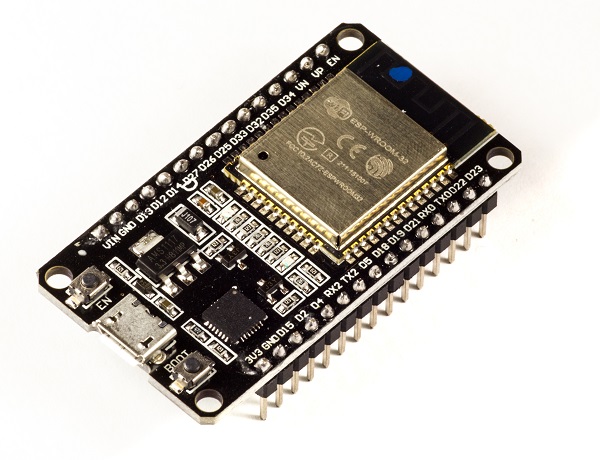
ESP32 dev board − Necessary
Micro USB Cable − Necessary for powering and programming the ESP32

MPU6050 module − Optional (You will need it only for the chapter specific to MPU6050)
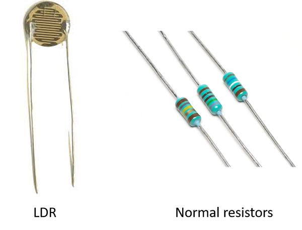
Light Dependent Resistor (LDR) with a normal resistor of comparable resistance or any other analog sensor − Optional (You will need these only for the ADC chapter)
OLED Display − Optional (You will need it only for the chapter specific to the OLED Interface)
Jumper wires − Optional (You will need these wires for interfacing ESP32 to MPU6050, LDR and/or OLED display)

A note on GitHub usage
As mentioned in the Overview part, a GitHub link is provided with each chapter that contains a code walkthrough. Several of these codes have been taken from the examples that come along with the ESP32 board in Arduino. Therefore, you need not make any extra effort to run them on your local machine. You can find them from File −> Examples in the Arduino IDE once you install the ESP32 board in Arduino (we have a separate chapter for that). Wherever an example code has been used, the exact path of the example code is mentioned.
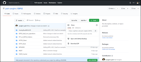
All the codes which are not present in examples can be found in the following repository − https://github.com/yash-sanghvi/ESP32. Now, if you wish to download and run these codes on your local machine, you need to do the following −
Click on the green button that reads 'Code'.
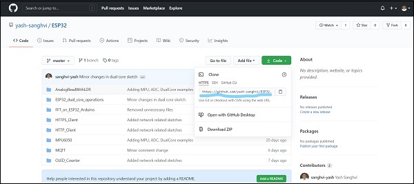
If you are new to Git, you can simply download the zip file and extract it into the folder of your choice. The subfolders contain the required Arduino (.ino) files which you can then open in the Arduino IDE and compile and flash into the ESP32.
If you are familiar with Git and have Git installed on your machine, you can copy the HTTPS address which is https://github.com/yash-sanghvi/ESP32.git, navigate to the folder where you wish to clone this repository, open your Git Command−Line and enter git clone https://github.com/yash-sanghvi/ESP32.git
If you are new to Git, you may be wondering why we should make the effort of cloning the repository, when downloading and extracting the zip will have the same effect. The answer is that downloading a zip is a one time process. In case, some changes happen to this repository in the future, the downloaded version in your local machine can't reflect those directly. You will need to download the zip again. If you clone the repository, you can fetch all the future changes by simply calling git pull. There's a lot more you can do with a clone. If there are multiple branches within the repository, you can switch branches just by git checkout branch−name. If you are downloading a zip, you will need to download a separate zip for each branch. The bottom line is that cloning is much more convenient in general. However, for this particular use case, since we don't anticipate major changes to this repository in the future and the master branch will only be of importance to you, you can go ahead and download zip, if you aren't very familiar with Git.
Have you noticed that a lot of everyday use things have become 'Smart' lately? There are Smart TVs, Smart ACs, Smart Refrigerators, and whatnot. What does the 'smartness' of these devices refer to? While the answer is somewhat different for each device, one common element of the smartness is 'connectedness'. Your TV gets connected to your WiFi so you can stream shows which you earlier watched only on your mobile phone. Your AC is connected to the internet. You can send a command from another city from your mobile phone, and the AC at your home will turn ON/OFF. Your watch is connected to your mobile phone (via BLE) and you can answer calls using your watch itself. All the things you commonly deal with are connected, as if in a net. It is an inter-net of things.

The above paragraph would have given you a feel of IoT. The definition of IoT, as per Wikipedia, is as follows −
The Internet of things (IoT) describes the network of physical objects - "things" − that are embedded with sensors, software, and other technologies for the purpose of connecting and exchanging data with other devices and systems over the Internet.
The above definition nails it. Things embedded with sensors, and containing software, sharing data with other devices/ systems over the Internet. This definition also clearly highlights two of the three major functional blocks of any IoT device −
Sense
Process and Store
Transmit
Sense
What do the IoT devices sense? They can sense anything worth sensing. If your IoT device is being installed in a garbage dump, it may check the garbage fill level. If your IoT device is being installed in a factory, it may sense the electricity consumption. If your IoT device is installed on a machine, it may sense the vibration signature of the machine to determine whether the machine is ON or OFF or cutting. If your device is installed on a vehicle, it may sense the movement and location of your vehicle.
Your IoT device will sense anything which can help you save costs, increase profits, or warn you about any impending catastrophe. Your traditional fire alarm is so close to being an IoT device. It senses smoke, processes it to determine if the smoke concentration is above the safe level. It just doesn't transmit this information anywhere. However, if you have all the fire alarms in the building connected to the internet, and a dashboard in the security room, showing which room has caught fire, your fire alarm will very much be an IoT device.
Process and Store
What processing/ storage happens onboard an IoT device? This answer depends a lot on your use case. There are IoT devices that do no processing onboard and simply transmit the raw sensor data to the servers. There are IoT devices that do live video processing onboard to identify objects/ people. It depends on the volume of your data, the RAM available, the final output desired, and the transmission bandwidth available. If your device gets a machine's vibration signature every millisecond, you will have 1000 readings in just one second. Sending this volume of data to the server may not make sense in some cases (especially if you are on a low bandwidth network like NB−IoT). In such cases, you may want to perform FFT onboard the device and just send the frequencies and amplitudes of the vibration to the server. If your device senses the temperature and humidity in the atmosphere once every 5 mins, you may just need the formula to convert the raw readings to temperature and humidity and send it across. Or you may just send the raw readings and let the server do the conversion. You may send every reading in this case.
Almost all IoT devices have some onboard memory to store the missed packets in case of a network error. Some devices have config files which also require onboard storage. Some devices keep the last X hours of data in their memory for future access. IoT devices that perform heavy processing onboard definitely require storage to collect sufficient data before the processing starts. For instance, if your device performs FFT on the vibration data after every 10,000 readings, it will need to store the incoming readings till the number reaches 10,000.
Transmit
How do IoT devices transmit data? Well, there are several solutions available. Some of them are −
Choosing the right transmission solution is a big decision in itself and depends a lot on the power available to you, your bandwidth requirements, communication distance, cost, and acceptable latency. Your smartwatch may use BLE to communicate with your mobile phone, your Smart TV may use WiFi, while a device installed in a vehicle may use a cellular network. An IoT device made for agricultural applications, like soil moisture measurement, especially in remote areas, may use LoRa to communicate with another device, which in turn may have a WiFi or Ethernet connection. The ultimate goal is almost always to get the data on a server, and/or display it to the user on a dashboard/app.
Wrapping up
If you are new to IoT, this chapter would have given you a good overview of what the fuss is all about. If this has got you excited, then move on to the next chapter, where we talk about ESP32, the System on Chip (SoC) microcontroller that this entire tutorial is all about. We discuss why ESP32 is popular in the IoT space and what functionalities it provides in the sensing, processing, storage, and transmission domains. See you there.
Introduction to ESP32
ESP32 is the SoC (System on Chip) microcontroller which has gained massive popularity recently. Whether the popularity of ESP32 grew because of the growth of IoT or whether IoT grew because of the introduction of ESP32 is debatable. If you know 10 people who have been part of the firmware development for any IoT device, chances are that 7−8 of them would have worked on ESP32 at some point. So what is the hype all about? Why has ESP32 become so popular so quickly? Let's find out.
Before we delve into the actual reasons for the popularity of ESP32, let's take a look at some of its important specifications. The specs listed below belong to the ESP32 WROOM 32 variant.−
Integrated Crystal− 40 MHz
Module Interfaces− UART, SPI, I2C, PWM, ADC, DAC, GPIO, pulse counter, capacitive touch sensor
Integrated SPI flash− 4 MB
ROM− 448 KB (for booting and core functions)
SRAM− 520 KB
Integrated Connectivity Protocols− WiFi, Bluetooth, BLE
On−chip sensor− Hall sensor
Operating temperature range− −40 − 85 degrees Celsius
Operating Voltage− 3.3V
Operating Current− 80 mA (average)
With the above specifications in front of you, it is very easy to decipher the reasons for ESP32's popularity. Consider the requirements an IoT device would have from its microcontroller (μC). If you've gone through the previous chapter, you'd have realized that the major operational blocks of any IoT device are sensing, processing, storage, and transmitting. Therefore, to begin with, the μC should be able to interface with a variety of sensors. It should support all the common communication protocols required for sensor interface: UART, I2C, SPI. It should have ADC and pulse counting capabilities. ESP32 fulfills all of these requirements. On top of that, it also can interface with capacitive touch sensors. Therefore, most common sensors can interface seamlessly with ESP32.
Secondly, the μC should be able to perform basic processing of the incoming sensor data, sometimes at high speeds, and have sufficient memory to store the data. ESP32 has a max operating frequency of 40 MHz, which is sufficiently high. It has two cores, allowing parallel processing, which is a further add-on. Finally, its 520 KB SRAM is sufficiently large for processing a large array of data onboard. Many popular processes and transforms, like FFT, peak detection, RMS calculation, etc. can be performed onboard ESP32. On the storage front, ESP32 goes a step ahead of the conventional microcontrollers and provides a file system within the flash. Out of the 4 MB of onboard flash, by default, 1.5 MB is reserved as SPIFFS (SPI Flash File System). Think of it as a mini−SD Card that lies within the chip itself. You can not only store data, but also text files, images, HTML and CSS files, and a lot more within SPIFFS. People have displayed beautiful Webpages on WiFi servers created using ESP32, by storing HTML files within SPIFFS.
Finally, for transmitting data, ESP32 has integrated WiFi and Bluetooth stacks, which have proven to be a game-changer. No need to connect a separate module (like a GSM module or an LTE module) for testing cloud communication. Just have the ESP32 board and a running WiFi, and you can get started. ESP32 allows you to use WiFi in Access Point as well as Station Mode. While it supports TCP/IP, HTTP, MQTT, and other traditional communication protocols, it also supports HTTPS. Yep, you heard that right. It has a crypto−core or a crypto-accelerator, a dedicated piece of hardware whose job is to accelerate the encryption process. So you cannot only communicate with your web server, you can do so securely. BLE support is also critical for several applications. Of course, you can interface LTE or GSM or LoRa modules with ESP32. Therefore, on the 'transmitting data' front as well, ESP32 exceeds expectations.
With so many features, ESP32 would be costing a fortune, right? That's the best part. ESP32 dev modules cost in the ballpark of ₹ 500. Not only that, the chip dimensions are quite small (25 mm x 18 mm, including the antenna area), allowing its use in devices requiring a very small form factor.
Finally, ESP32 can be programmed using the Arduino IDE, making the learning curve much less steep. Isn't that great? Are you excited to get your hands dirty with ESP32? Then let's start by installing the ESP32 board in the Arduino IDE in the next chapter. See you there.
Installing ESP32 Board in Arduino IDE
One very big advantage with ESP32, which has aided its quick adoption and massive popularity, is the provision for programming the ESP32 within the Arduino IDE.
Now, I should point out here that Arduino is not the only IDE that helps you compile code for ESP32 and flash it into the microcontroller. There is ESP−IDF which is the official development framework for ESP32, which provides much more flexibility in terms of configuration options. However, it is hardly as intuitive and user−friendly as the Arduino IDE, and if you are starting out with ESP32, Arduino IDE is ideal to get your hands dirty. Also, with the number of supporting libraries built for ESP32 in Arduino, courtesy of the huge developer community, there's hardly any functionality of ESP32 which can't be realized with the Arduino IDE. ESP-IDF is more suitable for the more advanced and experienced programmers, who need to stretch ESP32 to its limits. If you are one of those, you are looking for the ESP−IDF Getting Started Guide. Others can follow along.
Installation Steps
Now, to install the ESP32 board in the Arduino IDE, you need to follow the below steps −
Make sure you have Arduino IDE (preferably the latest version) installed on your machine
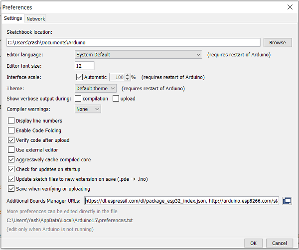
Open Arduino and go to File −> Preferences
In the Additional Boards Manager URL, enter
https://dl.espressif.com/dl/package_esp32_index.json
In case you have an existing JSON file's URL in the preferences (this is likely if you've installed ESP8266, stm32duino, or any such additional board in the IDE), you can just append the above path to the existing path, using a comma. An example is shown below, for ESP8266 and ESP32 boards −
http://arduino.esp8266.com/stable/package_esp8266com_index.json, https://dl.espressif.com/dl/package_esp32_index.json
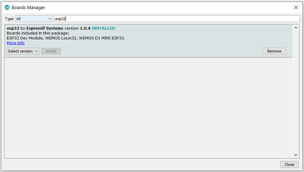
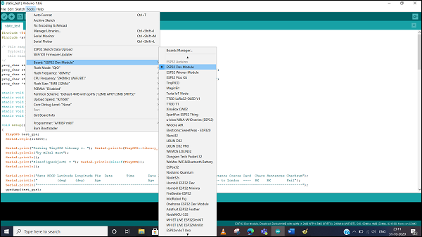
Go to Tools −> Board−> Boards Manager. A pop−up would open up. Search for ESP32 and install the esp32 by Espressif Systems board. The image below shows the board already installed because I had installed the board before preparing this tutorial.
Verifying the Installation
Once your ESP32 board has been installed, you can verify the installation by going to Tools −> Boards. You can see a whole bunch of boards under the ESP32 Arduino section. Choose the board of your choice. If you are not sure which board best represents the one you have, you can choose ESP32 Dev Module.
Next, connect your board to your machine using the USB Cable. You should see an additional COM Port under Tools−> Port. Select that additional port. In case you see multiple ports, you can disconnect the USB and see which port disappeared. That port corresponds to ESP32.
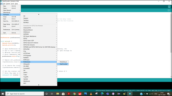
Once the port is identified, pick any one example sketch from File −> Examples. We will choose the StartCounter example from File −> Examples −> Preferences −> StartCounter.
Open that sketch, compile it and flash it into the ESP32 by clicking on the Upload button (the right arrow button, besides the Compile button).
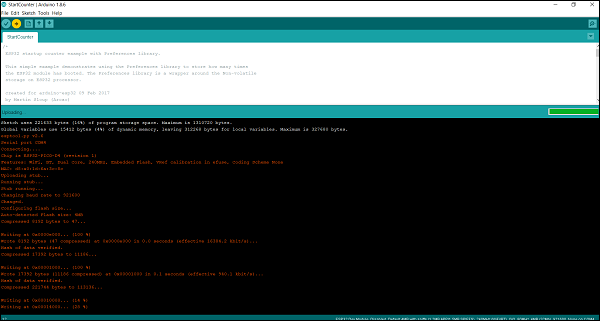
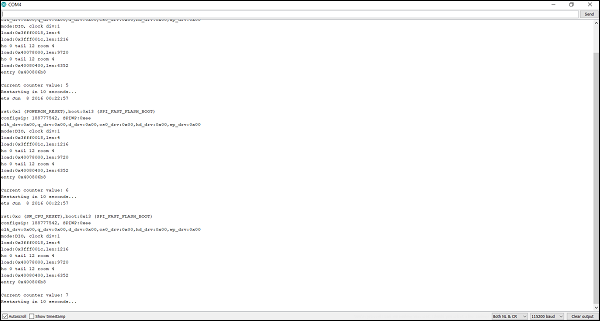
Then open the Serial Monitor using Tools −> Serial Monitor, or simply by pressing Ctrl + Shift + M on your keyboard. You should see the counter value getting incremented after every ESP32 restart.
Congratulations!! You've set up the environment for working with ESP32.
Setting up RTOS for dual-core & multi-threaded operation
A key feature of ESP32 that makes it so much more popular than its predecessor, ESP8266, is the presence of two cores on the chip. This means that we can have two processes executing in parallel on two different cores. Of course, you can argue that parallel operation can also be achieved on a single thread using FreeRTOS/ any other equivalent RTOS. However, there is a difference between two processes running in parallel on a single core, and they running in parallel on different cores. On a single core, often, one thread has to wait for the other to pause before it can begin execution. On two cores, parallel execution is literally parallel, because they are literally occupying different processors.
Sounds exciting? Let's get started with a real example, that demonstrates how to create two tasks and assign them to specific cores within ESP32.
Code Walkthrough
GitHub link: https://github.com/
To use FreeRTOS within the Arduino IDE, no additional imports are required. It comes inbuilt. What we need to do is define two functions that we wish to run on the two cores. They are defined first. One function evaluates the first 25 terms of the Fibonacci series and prints every 5th of them. It does so in a loop. The second function evaluates the sum of numbers from 1 to 100. It too does so in a loop. In other words, after calculating the sum from 1 to 100 once, it does so again, after printing the ID of the core it is executing on. We are not printing all the numbers, but only every 5th number in both the sequences, because both the cores will try to access the same Serial Monitor. Therefore, if we print every number, they will try to access the Serial Monitor at the same time frequently.
void print_fibonacci() {
   int n1 = 0;
   int n2 = 1;
   int term = 0;
   char print_buf[300];
   sprintf(print_buf, "Term %d: %d\n", term, n1);
   Serial.print(print_buf);
   term = term + 1;
   sprintf(print_buf, "Term %d: %d\n", term, n1);
   Serial.print(print_buf);
   for (;;) {
      term = term + 1;
      int n3 = n1 + n2;
      if(term%5 == 0){
      sprintf(print_buf, "Term %d: %d\n", term, n3);
      Serial.println(print_buf);
   }
   n1 = n2;
   n2 = n3;

   if (term >= 25) break;
   }
}
void sum_numbers() {
   int n1 = 1;
   int sum = 1;
   char print_buf[300];
   for (;;) {
      if(n1 %5 == 0){
         sprintf(print_buf, "                                                            Term %d: %d\n", n1, sum);
         Serial.println(print_buf);
      }
      n1 = n1 + 1;
      sum = sum+n1;
      if (n1 >= 100) break;
   }
}
void codeForTask1( void * parameter ) {
   for (;;) {
      Serial.print("Code is running on Core: ");Serial.println( xPortGetCoreID());
      print_fibonacci();
   }
}
void codeForTask2( void * parameter ) {
   for (;;) {
      Serial.print("                                                            Code is running on Core: ");Serial.println( xPortGetCoreID());
      sum_numbers();
   }
}
You can see above that we have shifted the print statement for Task 2 to the right. This will help us differentiate between the prints happening from Task 1 and Task 2.
Next we define task handles. Task handles serve the purpose of referencing that particular task in other parts of the code. Since we have two tasks, we will define two task handles.
TaskHandle_t Task1, Task2;
Now that the functions are ready, we can move to the setup part. Within setup(), we simply pin the two tasks to the respective cores. First, let me show you the code snippet.
void setup() {
   Serial.begin(115200);
   /*Syntax for assigning task to a core:
   xTaskCreatePinnedToCore(
                    coreTask,   // Function to implement the task
                    "coreTask", // Name of the task
                    10000,      // Stack size in words
                    NULL,       // Task input parameter
                    0,          // Priority of the task
                    NULL,       // Task handle.
                    taskCore);  // Core where the task should run
   */
   xTaskCreatePinnedToCore(    codeForTask1,    "FibonacciTask",    5000,      NULL,    2,    &Task1,    0);
   //delay(500);  // needed to start-up task1
   xTaskCreatePinnedToCore(    codeForTask2,    "SumTask",    5000,    NULL,    2,    &Task2,    1);
}
Now let's dive deeper into the xTaskCreatePinnedToCore function. As you can see, it takes a total of 7 arguments. Their description is as follows.
The first argument codeForTask1 is the function that will be executed by the task
The second argument "FibonacciTask" is the label or name of that task
The third argument 1000 is the stack size in bytes that is allotted to this task
The fourth argument NULL is the task input parameter. Basically, if you wish to input any parameter to the task, it goes here
The fifth argument 1 defines the priority of the task. The higher the value, the more is the priority of the task.
The sixth argument &Task1 is the Task Handle
The final argument 0 is the Code on which the task will run. If the value is 0, the task will run on Core 0. If it is 1, the task will run on Code 1.
Finally, the loop can be left empty, since the two tasks running on the two cores are of more importance here.
void loop() {}
You can see the output on the Serial Monitor. Note that there are no delays anywhere in the code. Therefore, both the series getting incremented shows that the computations are happening in parallel. The Core IDs printed on the Serial Monitor also confirm that.
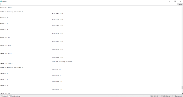
Please note that Arduino sketches, by default, run on Core 1. This can be verified using Serial.print( xPortGetCoreID()); So if you add some code in loop(), it will run as another thread on Core 1. In that case, Core 0 will have a single task running, while Core 1 will have two tasks running.
Interfacing ESP32 with MPU6050
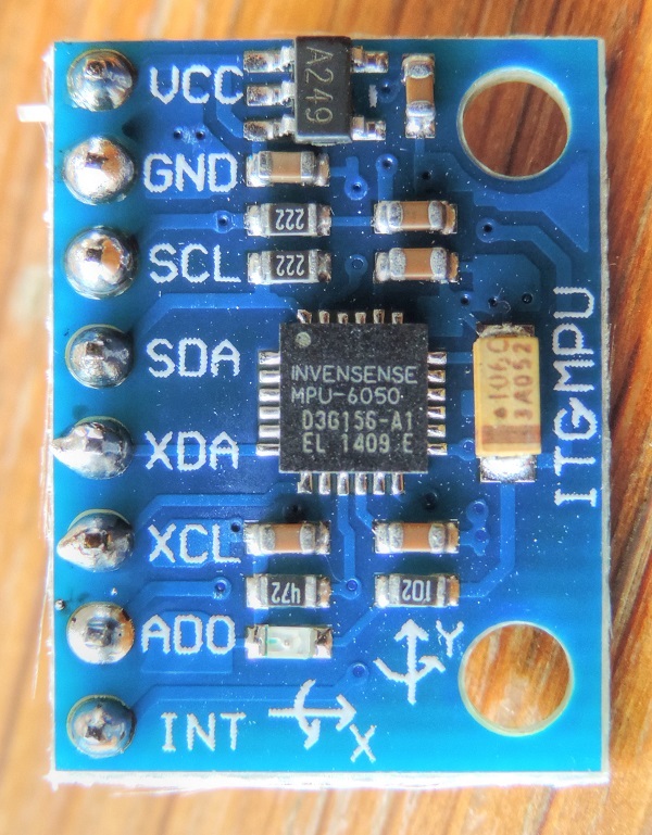
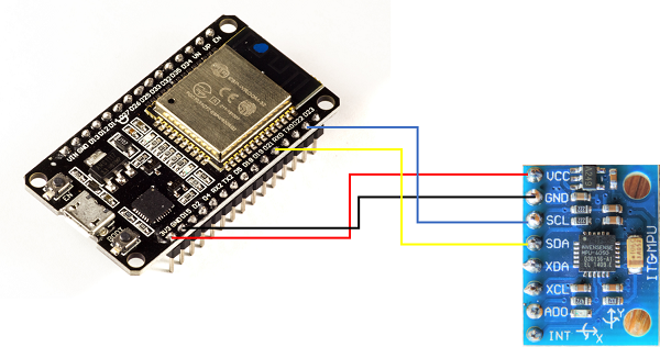
Accelerometers and Gyroscopes are widely used in Industrial IoT for measuring the health and operating parameters of various machines. MPU6050 is a popular six-axis accelerometer + gyroscope. It is a MEMS (Micro-Electro-Mechanical Systems) sensor, meaning it is very compact (as can be seen from the image below) and, for a wide range of frequencies, very accurate as well.
In this tutorial, we will see how to interface ESP32 with the MPU6050. In the process, you will learn about the usage of the I2C (Inter-Integrated Circuit) protocol, which will then enable you to interface the ESP32 with several sensors and peripherals which communicate using the I2C protocol. You will need your ESP32, an MPU6050, and a couple of jumper wires for this tutorial.
Connecting MPU6050 with ESP32
As shown in the image below, you need to connect the SDA line of MPU6050 to pin 21 on ESP32, SCL line to pin 22, GND to GND, and VCC to 3V3 pin. The other pins of MPU6050 need not be connected.
Code Walkthrough
GitHub Link − https://github.com/
ESP32, and Arduino in general refer to the I2C protocol as 'Wire'. Therefore the required library import is Wire.h
#include<Wire.h>
Next we define constants and global variables.
const int MPU_ADDR = 0x68; // I2C address of the MPU-6050
int16_t AcX, AcY, AcZ, Tmp, GyX, GyY, GyZ;
Every I2C device has a fixed address using which other devices identify it and communicate with it. For MPU6050, that address is 0x68. We will use it later when initializing the I2C communication with the MPU6050. We next move to the setup code.
void setup() {
   Serial.begin(115200);
   Wire.begin(21, 22, 100000); // sda, scl, clock speed
   Wire.beginTransmission(MPU_ADDR);
   Wire.write(0x6B);  // PWR_MGMT_1 register
   Wire.write(0);     // set to zero (wakes up the MPU−6050)
   Wire.endTransmission(true);
   Serial.println("Setup complete");
}
The first line is trivial. We are initiating communication with the serial monitor at 115200 baud rate. Next, we begin the I2C communication. For that, we provide 3 arguments to the Wire.begin() function.
These are the SDA and SCL pins and the clock speed. Now, I2C communication requires two lines: the Data line (SDA) and the Clock line (SCL). On ESP32, pins 21 and 22 are generally reserved for I2C, with 21 being SDA and 22 being SCL. For communicating with MPU6050, we have two speed options: 100kbit/s and 400kbit/s. We have chosen 100kHz here. You can choose the higher speed option as well if your use-case requires it.
Next, we indicate to the ESP32 that we want to communicate with the chip which has the address equal to MPU_ADDR, using the Wire.beginTransmission() command. At this point, you would have guessed that one ESP32 chip can communicate with multiple I2C peripherals. In fact, there are 128 unique addresses possible (address field is 7 bits long), and so the ESP32 can communicate with 128 different peripherals using I2C, provided all of them have different addresses.
In the next couple of lines, we are setting the PWR_MGMT_1 register of MPU6050 to 0. This is used to wake up the MPU6050. The address 0x6B of the PWR_MGMT_1 register is the address within MPU6050's memory.
It has nothing to do with the I2C address of MPU6050. Once the MPU is woken up, we end this particular transmission over I2C and our setup is complete, and we indicate that on the Serial Monitor using a print statement. Now let's jump into the loop. You will notice that we pass a boolean true as an argument to Wire.endTransmission. This tells the ESP32 to send a stop command and release the I2C lines. If we replace true with false, the ESP32 will send a restart instead of stop, keeping the connection active.
void loop() {
   Wire.beginTransmission(MPU_ADDR);
   Wire.write(0x3B);  // starting with register 0x3B (ACCEL_XOUT_H)
   Wire.endTransmission(true);
   Wire.beginTransmission(MPU_ADDR);
   Wire.requestFrom(MPU_ADDR, 14, true); // request a total of 14 registers
   AcX = Wire.read() −− 8 | Wire.read(); // 0x3B (ACCEL_XOUT_H) & 0x3C (ACCEL_XOUT_L)
   AcY = Wire.read() −− 8 | Wire.read(); // 0x3D (ACCEL_YOUT_H) & 0x3E (ACCEL_YOUT_L)
   AcZ = Wire.read() −− 8 | Wire.read(); // 0x3F (ACCEL_ZOUT_H) & 0x40 (ACCEL_ZOUT_L)
   Tmp = Wire.read() −− 8 | Wire.read(); // 0x41 (TEMP_OUT_H) &  0x42 (TEMP_OUT_L)
   GyX = Wire.read() −− 8 | Wire.read(); // 0x3B (ACCEL_XOUT_H) & 0x3C (ACCEL_XOUT_L)
   GyY = Wire.read() −− 8 | Wire.read(); // 0x3D (ACCEL_YOUT_H) & 0x3E (ACCEL_YOUT_L)
   GyZ = Wire.read() −− 8 | Wire.read(); // 0x3F (ACCEL_ZOUT_H) & 0x40 (ACCEL_ZOUT_L)


   Serial.print(AcX); Serial.print(" , ");
   Serial.print(AcY); Serial.print(" , ");
   Serial.print(AcZ); Serial.print(" , ");
   Serial.print(GyX); Serial.print(" , ");
   Serial.print(GyY); Serial.print(" , ");
   Serial.print(GyZ); Serial.print("\n");
}
In the loop, if you scan through the above code snippet, you will see that we perform a total of two transmissions. In the first one, we indicate to the MPU6050 the address from which we would like to start reading the data, or rather set the MPU6050's internal pointer to this particular address. In the second transmission, we tell the MPU that we request 14 bytes starting from the address sent earlier. Then we read the bytes one by one. You may notice that we don't have a Wire.endTransmission(true) command at the end of read. This is because the third argument of Wire.requestFrom(MPU,14,true) indicates to the ESP32 to send a stop command after reading the required number of bytes. Had we passed false instead of true, ESP32 would have sent a restart command instead of stop command.
Now, you might be wondering how was it determined that which register corresponds to which reading. The answer is the MPU6050 register map. It, as the name suggests, provides information on which value can be obtained from which register. Based on this map, we realized that we understand that 0x3B and 0x3C correspond to the higher and lower bytes of the 16−bit X−direction acceleration value. The next two registers (0x3D and 0x3E) contain the higher and lower bytes of the 16−bit Y−direction acceleration value, and so on. In between accelerometer and gyroscope readings, there are two bytes containing temperature readings, which we read and ignore, because we don't require them.So with this, you can successfully acquire data from MPU6050 on an ESP32. Congratulations!! Move on to the next tutorial for learning how to acquire data from an analog sensor on ESP32.
References
Interfacing ESP32 with Analog Sensors
Another important category of sensors that you need to interface with ESP32 is analog sensors. There are many types of analog sensors, LDRs (Light Dependent Resistors), current and voltage sensors being popular examples. Now, if you are familiar with how analogRead works on any Arduino board, like Arduino Uno, then this chapter will be a cakewalk for you because ESP32 uses the same functions. There are only a few nuances you should be aware of, that will be covered in this chapter.
A brief about the Analog to Digital Conversion (ADC) process
Every microcontroller which supports ADC will have a defined resolution and a reference voltage. The reference voltage is generally the supply voltage. The analog voltage provided to the ADC pin should be less than or equal to the reference voltage. The resolution indicates the number of bits that will be used to represent the digital value. Thus, if the resolution is 8 bits, then the value will be represented by 8 bits, and the maximum value possible is 255. This maximum value corresponds to the value of the reference voltage. The values for other voltages are often derived by scaling.
Thus, if the reference voltage is 5V and an 8−bit ADC is used, then 5V corresponds to a reading of 255, 1V corresponds to a reading of (255/5*1) = 51, 2V corresponds to a reading (255/5*2) = 102 and so on. If we had a 12 bit ADC, then 5V would correspond to a reading of 4095, 1V would correspond to a reading of (4095/5*1) = 819, and so on.
The reverse calculations can be performed similarly. If you get a value of 1000 on a 12 bit ADC with a reference voltage of 3.3V, then it corresponds to a value of (1000/4095*3.3) = 0.8V approximately. If you get a reading of 825 on a 10 bit ADC with a reference voltage of 5V, it corresponds to a value of (825/1023*5) = 4.03V approximately.
With the above explanation, it will be clear that both the reference voltage and the number of bits used for ADC determine the minimum possible voltage change that can be detected. If the reference voltage is 5V and the resolution is 12-bit, you have 4095 values to represent a voltage range of 0−5V. Thus, the minimum change that can be detected is 5V/4095 = 1.2mV. Similarly, for a 5V and 8-bit reference voltage, you have only 255 values to represent a range of 0-5V. Thus, the minimum change that can be detected is 5V/255 = 19.6mV, or about 16 times higher than the minimum change detected with a 12-bit resolution.
Connecting the ADC Sensor with ESP32
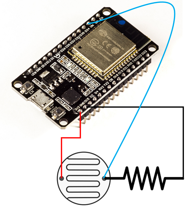
Considering the popularity and availability of the sensor, we will use an LDR for the demonstration. We will essentially connect LDR in series with a regular resistor, and feed the voltage at the point connecting the two resistors to the ADC pin of ESP32. Which pin? Well, there are lots of them. ESP32 boasts of 18 ADC pins (8 in channel 1 and 10 in channel 2). However, channel 2 pins cannot be used along with WiFi. And some pins of channel 1 are not exposed on some boards. Therefore, I generally stick to the following 6 pins for ADC− 32, 33, 34, 35, 36, 39. In the image shown below, an LDR with a resistance of 90K is connected to a resistor of resistance 150K. The free end of the LDR is connected to the 3.3V pin of ESP32 and the free end of the resistor is connected to GND. The common end of the LDR and the resistor is fed to the ADC pin 36 (VN) of ESP32.
Code Walkthrough
GitHub link − https://github.com/
The code here is straightforward. No libraries need to be included. We just define the LDR pin as a constant, initialize serial in the setup(), and set the resolution of the ADC. Here we have set a resolution of 10-bits (meaning the maximum value is 1023). By default the resolution is 12-bits and for ESP32, the minimum possible resolution is 9 bits.
const int LDR_PIN = 36;

void setup() {
   // put your setup code here, to run once:
   Serial.begin(115200);
   analogReadResolution(10); //default is 12. Can be set between 9-12.
}
In the loop, we just read the value from the LDR pin and print it to the serial monitor. Also, we convert it to voltage and print the corresponding voltage as well.
void loop() {
   // put your main code here, to run repeatedly:
   // LDR Resistance: 90k ohms
   // Resistance in series: 150k ohms
   // Pinouts:
   // Vcc −> 3.3 (CONNECTED TO LDR FREE END)
   // Gnd −> Gnd (CONNECTED TO RESISTOR FREE END)
   // Analog Read −> Vp (36) − Intermediate between LDR and resistance.
   int LDR_Reading = analogRead(LDR_PIN);
   float LDR_Voltage = ((float)LDR_Reading*3.3/1023);
   Serial.print("Reading: ");Serial.print(LDR_Reading); Serial.print("\t");Serial.print("Voltage: ");Serial.println(LDR_Voltage);
}
We have used 1023 as the divisor because we have set the ADC resolution to 10 bits. In case you change the ADC value to N, you need to change the divisor to (2^N −1). Now place your hand on the LDR
We have used 1023 as the divisor because we have set the ADC resolution to 10 bits. In case you change the ADC value to N, you need to change the divisor to (2^N −1). Now place your hand on the LDR, and see the effect on the voltage, and then flash a torch on the LDR and see the voltage swing to the opposite extreme on the Serial Monitor. That's it. You've successfully captured data from an analog sensor on ESP32.
References
Preferences in ESP32
Non−volatile storage is an important requirement for embedded systems. Often, we want the chip to remember a couple of things, like setup variables, WiFi credentials, etc. even between power cycles. It would be so inconvenient if we had to perform setup or config every time the device undergoes a power reset. ESP32 has two popular non-volatile storage methods: preferences and SPIFFS. While preferences are generally used for storing key-value pairs, SPIFFS (SPI Flash File System), as the name suggests, is used for storing files and documents. In this chapter, let's focus on preferences.
Preferences are stored in a section of the main flash memory with type as data and subtype as nvs. nvs stands for non−volatile storage. By default, 20 KB of space is reserved for preferences, so don't try to store a lot of bulky data in preferences. Use SPIFFS for bulky data (SPIFFS has 1.5 MB of reserved space by default). What kind of key−value pairs can be stored within preferences? Let's understand through the example code.
Code Walkthrough
We will use the example code provided. Go to File −> Examples −> Preferences −> StartCounter. It can also be found on GitHub.
This code keeps a count of how many times the ESP32 was reset. Therefore, every time it wakes up, it fetches the existing count from preferences, increments it by one, and saves the updated count back to preferences. It then resets the ESP32. You can see using the printed statements on the ESP32 that the value of the count is not lost between resets, that it is indeed non−volatile.
This code is very heavily commented, and therefore, largely, self-explanatory. Nevertheless, let's walk through the code.
We begin by including the Preferences library.
#include <Preferences.h>
Next, we create an object of Class Preferences.
Preferences preferences;
Now let's look at the setup line by line. We begin by initializing Serial.
void setup() {
   Serial.begin(115200);
   Serial.println();
Next, we open preferences with a namespace. Now, think of the preference storage like a bank locker−room. There are several lockers, and you open one at a time. The namespace is like the name of the locker. Within each locker, there are key−value pairs that you can access. If the locker whose name you mentioned does not exist, then it will be created, and then you can add key−value pairs to that locker. Why are there different lockers? To avoid clashes in the name. Say you have a WiFi library that uses preferences to store credentials and a BlueTooth library that also uses preferences to store credentials. Say both of these are being developed by different developers. What if both use the same key name credentials? This will obviously create a lot of confusion. However, if both of them have their keys in different lockers, there will be no confusion at all.
// Open Preferences with my-app namespace. Each application module, library, etc
// has to use a namespace name to prevent key name collisions. We will open storage in
// RW-mode (second parameter has to be false).
// Note: Namespace name is limited to 15 chars.
preferences.begin("my−app", false);
The second argument false of preferences.begin() indicates that we want to both read from and write to this locker. If it was true, we could only read from the locker, not write to it. Also, the namespace, as mentioned in the comments, shouldn't be more than 15 characters in length.
Next, the code has a couple of commented statements, which you can make use of depending on the requirement. One enables you to clear the locker, and the other helps you delete a particular key−value pair from the locker (having the key as "counter")
// Remove all preferences under the opened namespace
//preferences.clear();

// Or remove the counter key only
//preferences.remove("counter");
As a next step, we get the value associated with the key "counter". Now, for the first time when you run this program, there may be no such key existing. Therefore, we also provide a default value of 0 as an argument to the preferences.getUInt() function. What this tells ESP32 is that if the key "counter" doesn't exist, create a new key-value pair, with key as "counter" and value as 0. Also, note that we are using getUInt because the value is of type unsigned int. Other functions like getFloat, getString, etc. need to be called depending on the type of the value. The full list of options can be found here.
unsigned int counter = preferences.getUInt("counter", 0);
Next, we increment this count by one and print it on the Serial Monitor.
// Increase counter by 1
counter++;

// Print the counter to Serial Monitor
Serial.printf("Current counter value: %u\n", counter);
We then store this updated value back to non-volatile storage. We are basically updating the value for the key "counter". Next time the ESP32 reads the value of the key "counter", it will get the incremented value.
// Store the counter to the Preferences
preferences.putUInt("counter", counter);
Finally, we close the preferences locker and restart the ESP32 in 10 seconds.
// Close the Preferences
preferences.end();

// Wait 10 seconds
Serial.println("Restarting in 10 seconds...");
delay(10000);

// Restart ESP
ESP.restart();
}
Because we restart ESP32 before diving into the loop, the loop is never executed. Therefore, it is kept blank
void loop() {}
This example demonstrates quite well how ESP32 preferences storage is indeed non−volatile. When you check the printed statements on the Serial Monitor, you can see the count getting incremented between successive resets. This would not have happened with a local variable. It was only possible by using non−volatile storage through preferences.
References
SPIFFS in ESP32
In the previous chapter, we looked at preferences as one way of storing data in non−volatile storage and understood how they are used to store key-value pairs. In this one, we look at SPIFFS (SPI Flash File Storage), which is used for storing larger data in the form of files. Think of SPIFFS as a very small SD Card onboard the ESP32 chip itself. By default, about 1.5 MB of the onboard flash is allocated to SPIFFS. You can see that for yourself by going through Tools −> Partition Scheme.
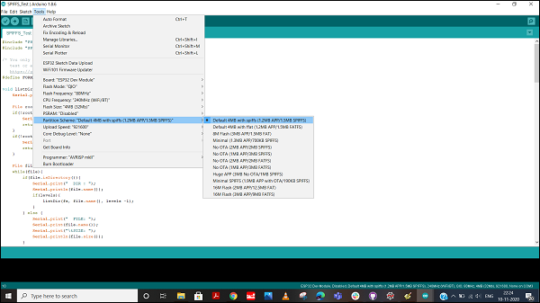
You can see that there are several other partition options available. However, let's not get there right now. Changing the partition scheme will anyway not be required for most of your applications. All the chapters in this tutorial will work well with the default partition scheme.
Now let's see the process of creating, modifying, reading, and deleting a file from SPIFFS, using an example.
Code Walkthrough
We will again use the example code provided. Go to File −> Examples −> SPIFFS −> SPIFFS_Test. This code is ideal for understanding all the file operations possible with SPIFFS. It can also be found on GitHub
We begin with the inclusion of two libraries: FS.h and SPIFFS.h. FS stands for File System.
#include "FS.h"
#include "SPIFFS.h"
Next, you see a macro definition, FORMAT_SPIFFS_IF_FAILED. There is an associated comment which suggests that you need to format the SPIFFS only the first time you run a test. What this means is that you can set the value of this macro to false after your first run. Formatting the SPIFFS takes time, and need not be done every time you run your code. Therefore, a practice that people follow is to have a separate code for formatting the SPIFFS, which they flash before flashing the main code. The main code doesn't include the format command. In this example though, for the sake of completeness, this macro has been kept as true.
/* You only need to format SPIFFS the first time you run a
   test or else use the SPIFFS plugin to create a partition
   https://github.com/me−no−dev/arduino−esp32fs−plugin */
#define FORMAT_SPIFFS_IF_FAILED true
Next, you can see that a number of functions have been defined for different file system operations. They are −
listDir − To list all directories
readFile − To read a specific file
writeFile − To write to a file (this overwrites the content already present in the file)
appendFile − To append content to a file (use this when you want to add to the existing content, not overwrite it
renameFile − To change the name of a file
deleteFile − To delete a file
void listDir(fs::FS &fs, const char * dirname, uint8_t levels){
   Serial.printf("Listing directory: %s\r\n", dirname);

   File root = fs.open(dirname);
   if(!root){
      Serial.println("− failed to open directory");
      return;
   }
   if(!root.isDirectory()){
      Serial.println(" − not a directory");
      return;
   }

   File file = root.openNextFile();
   while(file){
      if(file.isDirectory()){
         Serial.print("  DIR : ");
         Serial.println(file.name());
         if(levels){
            listDir(fs, file.name(), levels -1);
         }
      } else {
         Serial.print("  FILE: ");
         Serial.print(file.name());
         Serial.print("\tSIZE: ");
         Serial.println(file.size());
      }
      file = root.openNextFile();
   }
}

void readFile(fs::FS &fs, const char * path){
   Serial.printf("Reading file: %s\r\n", path);

   File file = fs.open(path);
   if(!file || file.isDirectory()){
       Serial.println("− failed to open file for reading");
       return;
   }

   Serial.println("− read from file:");
   while(file.available()){
      Serial.write(file.read());
   }
}

void writeFile(fs::FS &fs, const char * path, const char * message){
   Serial.printf("Writing file: %s\r\n", path);

   File file = fs.open(path, FILE_WRITE);
   if(!file){
      Serial.println("− failed to open file for writing");
      return;
   }
   if(file.print(message)){
      Serial.println("− file written");
   }else {
      Serial.println("− frite failed");
   }
}

void appendFile(fs::FS &fs, const char * path, const char * message){
   Serial.printf("Appending to file: %s\r\n", path);

   File file = fs.open(path, FILE_APPEND);
   if(!file){
      Serial.println("− failed to open file for appending");
      return;
   }
   if(file.print(message)){
      Serial.println("− message appended");
   } else {
      Serial.println("− append failed");
   }
}

void renameFile(fs::FS &fs, const char * path1, const char * path2){
   Serial.printf("Renaming file %s to %s\r\n", path1, path2);
   if (fs.rename(path1, path2)) {
      Serial.println("− file renamed");
   } else {
      Serial.println("− rename failed");
   }
}

void deleteFile(fs::FS &fs, const char * path){
   Serial.printf("Deleting file: %s\r\n", path);
   if(fs.remove(path)){
      Serial.println("− file deleted");
   } else {
      Serial.println("− delete failed");
   }
}
Note that all of the above functions aren't asking for a file name. They are asking for the full file path. Because this is a file system. You could have directories, subdirectories, and files within those subdirectories. Therefore, ESP32 needs to know the full path of the file you want to operate on.
Next comes a function that isn't exactly a file operation function − testFileIO. This is more of a time benchmarking function. It does the following −
Writes about 1 MB (2048 * 512 bytes) of data to the file path that you provide and measures the write time
Reads the same file and measures the read time
void testFileIO(fs::FS &fs, const char * path){
   Serial.printf("Testing file I/O with %s\r\n", path);

   static uint8_t buf[512];
   size_t len = 0;
   File file = fs.open(path, FILE_WRITE);
   if(!file){
      Serial.println("− failed to open file for writing");
      return;
   }

   size_t i;
   Serial.print("− writing" );
   uint32_t start = millis();
   for(i=0; i<2048; i++){
      if ((i & 0x001F) == 0x001F){
         Serial.print(".");
      }
      file.write(buf, 512);
   }
   Serial.println("");
   uint32_t end = millis() − start;
   Serial.printf(" − %u bytes written in %u ms\r\n", 2048 * 512, end);
   file.close();

   file = fs.open(path);
   start = millis();
   end = start;
   i = 0;
   if(file && !file.isDirectory()){
      len = file.size();
         size_t flen = len;
         start = millis();
         Serial.print("− reading" );
         while(len){
            size_t toRead = len;
            if(toRead > 512){
                toRead = 512;
            }
            file.read(buf, toRead);
            if ((i++ & 0x001F) == 0x001F){
              Serial.print(".");
            }
            len −= toRead;
         }
      Serial.println("");
      end = millis() - start;
      Serial.printf("- %u bytes read in %u ms\r\n", flen, end);
      file.close();
   } else {
      Serial.println("- failed to open file for reading");
   }
}
Note that the buf array is never initialized with any value. We may very well be writing garbage bytes to the file. That doesn't matter because the purpose of the function is to measure the write time and the read time.
Once our functions have been defined, we move on to the setup, where the invocation of each of these functions is shown.
void setup(){
   Serial.begin(115200);
   if(!SPIFFS.begin(FORMAT_SPIFFS_IF_FAILED)){
      Serial.println("SPIFFS Mount Failed");
      return;
   }
   listDir(SPIFFS, "/", 0);
   writeFile(SPIFFS, "/hello.txt", "Hello ");
   appendFile(SPIFFS, "/hello.txt", "World!\r\n");
   readFile(SPIFFS, "/hello.txt");
   renameFile(SPIFFS, "/hello.txt", "/foo.txt");
   readFile(SPIFFS, "/foo.txt");
   deleteFile(SPIFFS, "/foo.txt");
   testFileIO(SPIFFS, "/test.txt");
   deleteFile(SPIFFS, "/test.txt");
   Serial.println( "Test complete" );
}
The setup does essentially the following −
It first initializes the SPIFFS using SPIFFS.begin(). The macro defined at the beginning is used here. When true, it formats the SPIFFS (time−consuming); when false, it initializes the SPIFFS without formatting.
It then lists all the directories at the root level. Note that we have specified levels as 0. Therefore, we are not listing the subdirectories within the directories. You can increase the nesting by incrementing the levels argument.
It then writes "Hello" to a file hello.txt in the root. (the file will get created if it doesn't exist)
It then reads back hello.txt
It then renames hello.txt to foo.txt
It then reads foo.txt to see if the rename worked. You should see "Hello" printed because that's what is stored in the file.
It then deletes foo.txt
It then performs the testFileIO routine on a new file test.txt
Once the routine is performed, it deletes test.txt
That's it. This example code very nicely lists down and tests all the functions you may want to use with SPIFFS. You can go ahead and modify this code, and play around with the different functions.
Since we don't want to perform any recurring activity here, the loop is blank.
void loop(){
}
The output shown in the Serial Monitor will perhaps look like the image below −
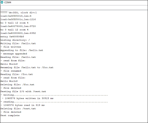
Note − If in case you get "SPIFFS Mount Failed" on running the sketch, set the value of FORMAT_SPIFFS_IF_FAILED to false and try again.
References
Interfacing OLED Display with ESP32
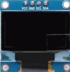
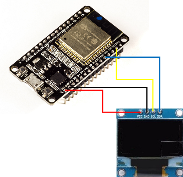
The combination of OLED with ESP32 is so popular that there are some boards of ESP32 with the OLED integrated. We'll, however, assume that you will be using a separate OLED module with your ESP32 board. If you have an OLED module, it perhaps looks like the image below.
Connecting the OLED Display Module to ESP32
Like the MPU6050 module that we discussed in a previous chapter, the OLED module also generally uses I2C for communication. Therefore, the connection will be similar to the MPU6050 module. You need to connect the SDA line to pin 21 on ESP32, SCL line to pin 22, GND to GND, and VCC to 3V3 pin
Library for OLED Display
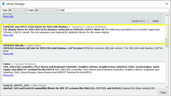
There are a number of libraries available for interfacing the OLED display with ESP32. You are free to use anyone you are comfortable with. For this example, we will use the 'ESP8266 and ESP32 OLED driver for SSD1306 displays, by ThingPulse, Fabrice Weinberg'. You can install this library from Tools −> Manage Libraries. It can also be found on GitHub
Code Walkthrough
The code becomes very simple thanks to the library we just installed. We will run a counter code, which will just count the seconds since the last reset and print them on the OLED module. The code can be found on GitHub
We begin with the inclusion of the SSD1306 library.
#include "SSD1306Wire.h"
Next, we define the OLED pins and its I2C address. Note that some OLED modules contain an additional Reset pin. A good example is the ESP32 TTGO board, which comes with an inbuilt OLED display. For that board, pin 16 is the reset pin. If you are connecting an external OLED module to your ESP32, you will most likely not use the Reset pin. The I2C address of 0x3c is generally common for all OLED modules.
//OLED related variables
#define OLED_ADDR   0x3c
#define OLED_SDA    21//4     //TTGO board without SD Card has OLED SDA connected to pin 4 of ESP32
#define OLED_SCL    22//15    //TTGO board without SD Card has OLED SCL connected to pin 15 of ESP32
#define OLED_RST    16        //Optional, TTGO board contains OLED_RST connected to pin 16 of ESP32
Next, we create the OLED display object and the counter variable.
SSD1306Wire  display(OLED_ADDR, OLED_SDA, OLED_SCL);
int counter = 0;
After that, we define two functions. One for initializing the OLED display (this function is redundant if your OLED module doesn't contain a reset pin), and the other for printing text messages on the OLED Display. The showOLEDMessage() function breaks down the OLED display area into 3 lines and asks for 3 strings, one for each line.
void initOLED() {
   pinMode(OLED_RST, OUTPUT);
   //Give a low to high pulse to the OLED display to reset it
   //This is optional and not required for OLED modules not containing a reset pin
   digitalWrite(OLED_RST, LOW);
   delay(20);
   digitalWrite(OLED_RST, HIGH);
}
void showOLEDMessage(String line1, String line2, String line3) {
   display.init();                        // clears screen
   display.setFont(ArialMT_Plain_16);
   display.drawString(0, 0, line1);       //  adds to buffer
   display.drawString(0, 20, line2);
   display.drawString(0, 40, line3);
   display.display();                     // displays content in buffer
}
Finally, in the setup, we just initialize the OLED display, and in the loop, we just utilize the first two lines of the display to show the counter.
void setup() {
   // put your setup code here, to run once:
   initOLED();
}
void loop() {
   // put your main code here, to run repeatedly
   showOLEDMessage("Num seconds is: ", String(counter), "");
   delay(1000);
   counter = counter+1;
}
That's it. Congratulations on displaying your first text statements on the OLED display.
WiFi on ESP32
The availability of a WiFi stack is one of the main differentiators between ESP32 and other microcontrollers. This chapter will give you a brief overview of the various WiFi modes available on ESP32. Subsequent chapters cover the transmission of data of WiFi using HTTP, HTTPS, and MQTT. There are 3 primary modes in which the WiFi can be configured on ESP32:
Station Mode − This is like the WiFi client mode. The ESP32 connects to an available WiFi field which in turn is connected to your internet. This is exactly similar to connecting your mobile phone to an available WiFi network.
Access Point Mode − This is equivalent to turning on the hotspot on your mobile phone so that other devices can connect to it. Similarly, ESP32 creates a WiFi field around itself that other devices can connect to. ESP32, however, does not have internet access by itself. Therefore, with this mode, you can generally display only a couple of webpages hardcoded into ESP32's memory. This mode is generally used to perform device setup during installation. Say you are taking your ESP32 to an unknown client site whose WiFi credentials you don't know beforehand. You will program the ESP32 to start operation in the Access Point mode. As soon as your mobile phone connects to the WiFi field created by ESP32, a page can open up (Captive Portal) and it will prompt you to enter WiFi credentials. Once you enter those credentials, the ESP32, will switch to station mode and try to connect to the available WiFi network using the credentials provided.
Combined AP-STA mode − As you might have guessed, in this mode, ESP32 is connected to an existing WiFi network and at the same time it is creating its own field, which other devices can connect to.
Most of the time, you will be using the ESP32 in the station mode. In all the 3 subsequent chapters as well, we will be using the ESP32 in the station mode. However, you should know about the AP mode as well and you are encouraged to explore examples of the AP mode yourself.
Transmitting data over WiFi using HTTP
HTTP (HyperText Transfer Protocol) is one of the most common forms of communications and with ESP32 we can interact with any web server using HTTP requests. Let's understand how in this chapter.
A brief about HTTP requests
The HTTP request happens between a client and a server. A server, as the name suggests, 'serves' information to the client on request. A web server serves web pages generally. For instance, when you type https://www.linkedin.com/login in your internet browser, your PC or laptop acts as a client and requests for the page corresponding to the /login address, from the server hosting linkedin.com. You get an HTML page in return, which is then displayed by your browser.
HTTP follows the request-response model, meaning that communication is always initiated by the client. The server cannot talk to any client out−of−the−blue, or can't start communication with any client. The communication always has to be initiated by the client in the form of a request and the server can only respond to that request. The response of the server contains the status code (remember 404? That's a status code) and, if applicable, the content requested. The list of all status codes can be found here.
Now, how does a server identify an HTTP request? Through the structure of the request. An HTTP request follows a fixed structure which consists of 3 parts:
The request line followed by carriage return line feed (CRLF = \r\n)
Zero or more header lines followed by CRLF and an empty line, again followed by CRLF
Optional body
This is how a typical HTTP request looks like:
POST / HTTP/1.1         //Request line, containing request method (POST in this case)
Host: www.example.com   //Headers
                        //Empty line between headers
key1=value1&key2=value2   //Body
This is how a server response looks like −
HTTP/1.1 200 OK                     //Response line; 200 is the status code
Date: Mon, 23 May 2005 22:38:34 GMT //Headers
Content-Type: text/html; charset=UTF-8
Content-Length: 155
Last-Modified: Wed, 08 Jan 2003 23:11:55 GMT
Server: Apache/1.3.3.7 (Unix) (Red-Hat/Linux)
ETag: "3f80f−1b6−3e1cb03b"
Accept-Ranges: bytes
Connection: close
                                    //Empty line between headers and body
<html>
  <head>
    <title>An Example Page</title>
  </head>
  <body>
    <p>Hello World, this is a very simple HTML document.</p>
  </body>
</html>
In fact, there is a very good tutorial on HTTP request structure on TutorialsPoint itself. It also introduces you to the various request methods (GET, POST, PUT, etc.). For this chapter, we will be concerned with the GET and POST methods.
The GET request contains all parameters in the form of a key value pair in the request URL itself. For example, if instead of POST, the same example request above was to be sent using GET, it would look like:
GET /test/demo_form.php?key1=value1&key2=value2 HTTP/1.1   //Request line
Host: www.example.com                                     //Headers
                                                          //No need for a body
The POST request, as you would have guessed by now, contains the parameters in the body instead of the URL. There are several more differences between GET and POST, which you can read here. But the crux is that you will use POST for sharing sensitive information, like passwords, with the server.
Code Walkthrough
For this chapter, we will write our HTTP request from scratch. There are libraries like httpClient available specifically for handling the ESP32 HTTP requests which take care of constructing the HTTP requests, but we will construct our request ourselves. That gives us much more flexibility. We will be restricting to the ESP32 Client mode for this tutorial. The HTTP server mode is also possible with ESP32, but that is for you to explore.
We will be using httpbin.org as our server. It is basically built for you to test your HTTP requests. You can test GET, POST, and a variety of other methods using this server. See this.
The code can be found on GitHub
We begin with the inclusion of the WiFi library.
#include <WiFi.h>
Next, we will define some constants. For HTTP, the port that is used is 80. That is the standard. Similarly, we use 443 for HTTPS, 21 for FTP, 53 for DNS, and so on. These are reserved port numbers.
const char* ssid = "YOUR_SSID";
const char* password = "YOUR_PASSWORD";

const char* server = "httpbin.org";
const int port = 80;
Finally, we create our WiFiClient object.
WiFiClient client
In the setup, we simply connect to the WiFi in the station mode using the credentials provided.
void setup() {
   Serial.begin(115200);
   WiFi.mode(WIFI_STA);          //The WiFi is in station mode. The other is the softAP mode
   WiFi.begin(ssid, password);
   while (WiFi.status() != WL_CONNECTED) {
      delay(500);
      Serial.print(".");
   }
   Serial.println("");  Serial.print("WiFi connected to: "); Serial.println(ssid);  Serial.println("IP address: ");  Serial.println(WiFi.localIP());
   delay(2000);
}
The loop becomes important here. That's where the HTTP request gets executed. We first begin by reading the Chip ID of our ESP32. We will be sending that as a parameter to the server along with our name. We will construct the body of our HTTP request using these parameters.
void loop() {
   int  conn;
   int chip_id = ESP.getEfuseMac();;
   Serial.printf("  Flash Chip id = %08X\t", chip_id);
   Serial.println();
   Serial.println();
   String body = "ChipId=" + String(chip_id) + "&SentBy=" + "your_name";
   int body_len = body.length();
Notice the & before the SentBy field. & is used as a separator between different key-value pairs in the HTTP requests. Next, we connect to the server.
Serial.println(".....");
Serial.println(); Serial.print("For sending parameters, connecting to ");      Serial.println(server);
conn = client.connect(server, port);
POST Request
If our connection is successful, client.connect() will return 1. We check that before making the request.
if (conn == 1)  {
   Serial.println(); Serial.print("Sending Parameters...");
   //Request
   client.println("POST /post HTTP/1.1");
   //Headers
   client.print("Host: "); client.println(server);
   client.println("Content-Type: application/x−www−form−urlencoded");
   client.print("Content-Length: "); client.println(body_len);
   client.println("Connection: Close");
   client.println();
   //Body
   client.println(body);
   client.println();

   //Wait for server response
   while (client.available() == 0);

   //Print Server Response
   while (client.available()) {
      char c = client.read();
      Serial.write(c);
   }
} else {
   client.stop();
   Serial.println("Connection Failed");
}
As you can see, we use the client.print() or client.println() for sending our request lines. The request, headers, and body are clearly indicated via comments. In the Request line, POST /post HTTP/1.1 is equivalent to POST http://httpbin.org/post HTTP/1.1. Since we have already mentioned the server in the client.connect(server,port), it is understood that /post refers to the server/post URL.
For POST requests especially, the Content-Length header is very important. Without it, several servers assume that the content-length is 0, meaning there is no body. The Content-Type has been kept as application/x−www−form−urlencoded because our body represents a form data. In a typical form submission, you will have keys like Name, Address, etc., and corresponding values. You can have several other content types. For the full list, see this.
The Connection: Close header tells the server to close the connection after the request has been processed. You could have alternatively send Connection: Keep-Alive if you wanted the connection to be kept alive after the request was processed.
These are just some of the headers that we could have included. The full list of HTTP headers can be found here.
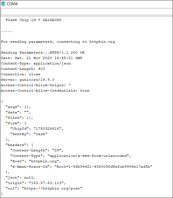
Now, the httpbin.org/post URL typically just echoes back our body. A sample response is the following −
HTTP/1.1 200 OK
Date: Sat, 21 Nov 2020 16:25:47 GMT
Content−Type: application/json
Content−Length: 402
Connection: close
Server: gunicorn/19.9.0
Access−Control−Allow−Origin: *
Access−Control−Allow−Credentials: true
{
   "args": {},
   "data": "",
   "files": {},
   "form": {
      "ChipId": "1780326616",
      "SentBy": "Yash"
   },
   "headers": {
      "Content−Length": "34",
      "Content−Type": "application/x−www−form−urlencoded",
      "Host": "httpbin.org",
      "X-Amzn−Trace−Id": "Root=1−5fb93f8b−574bfb57002c108a1d7958bb"
   },
   "json": null,
   "origin": "183.87.63.113",
   "url": "http://httpbin.org/post"
}
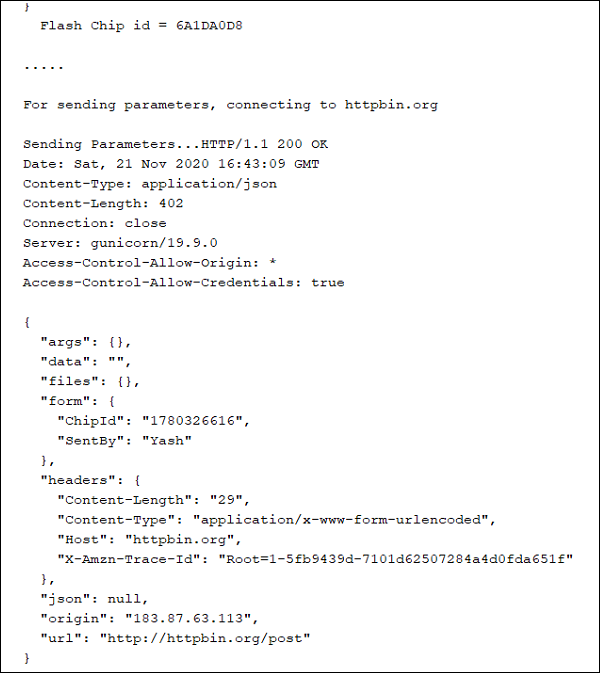
As you can see, the content of the POST body has been echoed back in the "form" field. You should see something similar to the above printed on your serial monitor. Also note the URL field. It clearly shows that the /post address in the request line was interpreted as http://httpbin.org/post.
Finally, we will wait for 5 seconds, before ending the loop, and thus, making the request again.
  delay(5000);
}
GET Request
At this point, you would be wondering, what changes would you need to make to convert this POST request to GET request. It is quite simple actually. You would, first of all, invoke the /get address instead of /post. Then you'll append the content of the body to the URL after a ? sign. Finally, you will replace the method to GET. Also, the Content-Length and Content−Type headers are no longer required, since your body is empty. Thus, your request block would look like −
if (conn == 1) {
   String path = String("/get") + String("?") +body;
   Serial.println(); Serial.print("Sending Parameters...");
   //Request
   client.println("GET "+path+" HTTP/1.1");
   //Headers
   client.print("Host: "); client.println(server);
   client.println("Connection: Close");
   client.println();
   //No Body

   //Wait for server response
   while (client.available() == 0);

   //Print Server Response
   while (client.available()) {
      char c = client.read();
      Serial.write(c);
   }
} else {
   client.stop();
   Serial.println("Connection Failed");
}
The corresponding response would look like −
HTTP/1.1 200 OK
Date: Tue, 17 Nov 2020 18:05:34 GMT
Content-Type: application/json
Content-Length: 497
Connection: close
Server: gunicorn/19.9.0
Access-Control−Allow−Origin: *
Access-Control-Allow-Credentials: true

{
   "args": {
      "ChipID": "3F:A0:A1:77:0D:84",
      "SentBy": "Yash"
   },
   "headers": {
      "Accept": "*/*",
      "Accept-Encoding": "deflate, gzip",
      "Host": "httpbin.org",
      "User-Agent": "Mozilla/5.0 (Windows NT 10.0; Win64; x64) AppleWebKit/537.36 (KHTML, like Gecko) Chrome/86.0.4240.198 Safari/537.36",
      "X−Amzn−Trace−Id": "Root=1−5fb410ee−3630963b0b7980c959c34038"
   },
   "origin": "206.189.180.4",
   "url": "https://httpbin.org/get?ChipID=3F:A0:A1:77:0D:84&SentBy=Yash"
}
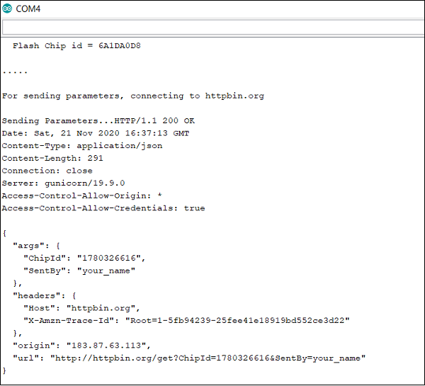
As you can see, the parameters send to the server are now returned in the args field, because they were sent as arguments in the URL itself.
Congratulations!! You've successfully sent your HTTP requests using ESP32.
References
Transmitting data over WiFi using HTTPS
We looked at transmitting data over HTTP using ESP32 in the previous chapter. In this one, we will transmit data over HTTPS. The S in HTTPS stands for 'Secure'. Basically, whatever data you transmit is encrypted using Transport Layer Security (TLS). This means that if someone is eavesdropping on your communication, they won't understand what you've transmitted. Instead, what they'll get is some gibberish. Covering how HTTPS works is beyond the scope of this chapter. But a simple Google search will provide several useful resources for you to get started. In this chapter, we will see how to implement HTTPS on ESP32.
Converting any HTTP request to HTTPS on ESP32
In general, if you have a code written for sending an HTTP request to the server, you can convert it to HTTPS following these simple steps −
Change the library from WiFiClient to WiFiClientSecure (you need to include WiFiClientSecure.h)
Change the port from 80 to 443
There is an optional fourth step: Add CA Certificate for the server. This step is optional because it doesn't affect the security of the communication. It just assures you that you are communicating with the correct server. If you don't provide the CA Certificate, your communication will still be secure.
Code Walkthrough
The code you see below is very similar to the one used for the HTTP communication. You are strongly advised to revisit that chapter. In this walkthrough, we will simply highlight the parts that are different from the HTTP code.
The code can be found on GitHub
We begin with the inclusion of the WiFi library. We also need to include the WiFiClientSecure library here.
#include <WiFi.h>
#include <WiFiClientSecure.h>
Next, we will define the constants. Note that the port is now 443 instead of 80.
const char* ssid = "YOUR_SSID";
const char* password = "YOUR_PASSWORD";

const char* server = "httpbin.org";
const int port = 443;
Next, instead of the WiFiClient object, we create the WiFiClientSecure object.
WiFiClientSecure client;
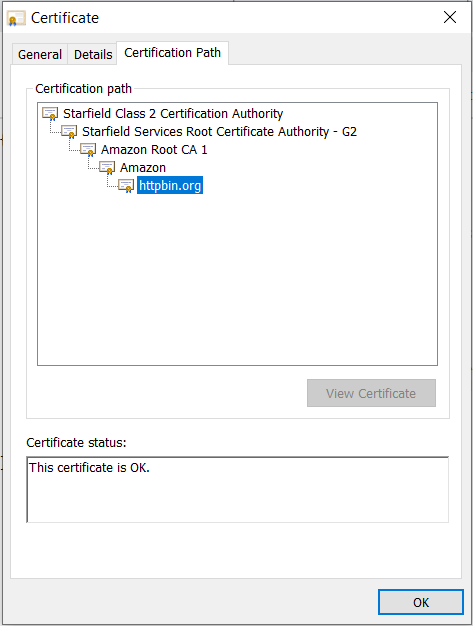
Next, we define the CA certificate for our server (httpbin.org). Now, you may be wondering how to get the CA certificate for our server. Detailed steps are given here to get the CA certificate of any server using Google Chrome. In that same post, a note on the validity of CA certificates has been provided, and it is recommended to use the certificate of the Certification Authority, instead of the certificate of the server, especially for applications where you just program the device once and send it out in the field for years. The Certification Authority's certificate has a much longer validity (15+ years), compared to the server's certificate validity (1−2 years). Therefore, we are using the certificate of the Starfield Class 2 Certification Authority (valid till 2034), instead of the certificate of httpbin.org (valid till Feb 2021).
const char* ca_cert = \
"-----BEGIN CERTIFICATE-----\n" \
"MIIEDzCCAvegAwIBAgIBADANBgkqhkiG9w0BAQUFADBoMQswCQYDVQQGEwJVUzEl\n"\
"MCMGA1UEChMcU3RhcmZpZWxkIFRlY2hub2xvZ2llcywgSW5jLjEyMDAGA1UECxMp\n"\
"U3RhcmZpZWxkIENsYXNzIDIgQ2VydGlmaWNhdGlvbiBBdXRob3JpdHkwHhcNMDQw\n"\
"NjI5MTczOTE2WhcNMzQwNjI5MTczOTE2WjBoMQswCQYDVQQGEwJVUzElMCMGA1UE\n"\
"ChMcU3RhcmZpZWxkIFRlY2hub2xvZ2llcywgSW5jLjEyMDAGA1UECxMpU3RhcmZp\n"\
"ZWxkIENsYXNzIDIgQ2VydGlmaWNhdGlvbiBBdXRob3JpdHkwggEgMA0GCSqGSIb3\n"\
"DQEBAQUAA4IBDQAwggEIAoIBAQC3Msj+6XGmBIWtDBFk385N78gDGIc/oav7PKaf\n"\
"8MOh2tTYbitTkPskpD6E8J7oX+zlJ0T1KKY/e97gKvDIr1MvnsoFAZMej2YcOadN\n"\
"+lq2cwQlZut3f+dZxkqZJRRU6ybH838Z1TBwj6+wRir/resp7defqgSHo9T5iaU0\n"\
"X9tDkYI22WY8sbi5gv2cOj4QyDvvBmVmepsZGD3/cVE8MC5fvj13c7JdBmzDI1aa\n"\
"K4UmkhynArPkPw2vCHmCuDY96pzTNbO8acr1zJ3o/WSNF4Azbl5KXZnJHoe0nRrA\n"\
"1W4TNSNe35tfPe/W93bC6j67eA0cQmdrBNj41tpvi/JEoAGrAgEDo4HFMIHCMB0G\n"\
"A1UdDgQWBBS/X7fRzt0fhvRbVazc1xDCDqmI5zCBkgYDVR0jBIGKMIGHgBS/X7fR\n"\
"zt0fhvRbVazc1xDCDqmI56FspGowaDELMAkGA1UEBhMCVVMxJTAjBgNVBAoTHFN0\n"\
"YXJmaWVsZCBUZWNobm9sb2dpZXMsIEluYy4xMjAwBgNVBAsTKVN0YXJmaWVsZCBD\n"\
"bGFzcyAyIENlcnRpZmljYXRpb24gQXV0aG9yaXR5ggEAMAwGA1UdEwQFMAMBAf8w\n"\
"DQYJKoZIhvcNAQEFBQADggEBAAWdP4id0ckaVaGsafPzWdqbAYcaT1epoXkJKtv3\n"\
"L7IezMdeatiDh6GX70k1PncGQVhiv45YuApnP+yz3SFmH8lU+nLMPUxA2IGvd56D\n"\
"eruix/U0F47ZEUD0/CwqTRV/p2JdLiXTAAsgGh1o+Re49L2L7ShZ3U0WixeDyLJl\n"\
"xy16paq8U4Zt3VekyvggQQto8PT7dL5WXXp59fkdheMtlb71cZBDzI0fmgAKhynp\n"\
"VSJYACPq4xJDKVtHCN2MQWplBqjlIapBtJUhlbl90TSrE9atvNziPTnNvT51cKEY\n"\
"WQPJIrSPnNVeKtelttQKbfi3QBFGmh95DmK/D5fs4C8fF5Q=\n"\
"-----END CERTIFICATE-----\n";
In the setup, we connect to the WiFi in the station mode using the credentials provided, like before. Here, we have the additional step of setting the CA Certificate for our WiFiSecureClient. By doing this, we are telling the client that only communicate with the server if its CA certificate matches the one provided.
void setup() {
   Serial.begin(115200);
   WiFi.mode(WIFI_STA);                    //The WiFi is in station mode. The    other is the softAP mode
   WiFi.begin(ssid, password);
   while (WiFi.status() != WL_CONNECTED) {
      delay(500);
      Serial.print(".");
   }
   Serial.println("");  Serial.print("WiFi connected to: "); Serial.println(ssid);  Serial.println("IP address: ");  Serial.println(WiFi.localIP());
   client.setCACert(ca_cert);            //Only communicate with the server if the CA certificates match
   delay(2000);
}
The loop is exactly the same as the one used in the HTTP example.
void loop() {
   int  conn;
   int chip_id = ESP.getEfuseMac();;
   Serial.printf("  Flash Chip id = %08X\t", chip_id);
   Serial.println();
   Serial.println();
   String body = "ChipId=" + String(chip_id) + "&SentBy=" + "your_name";
   int body_len = body.length();

   Serial.println(".....");
   Serial.println(); Serial.print("For sending parameters, connecting to "); Serial.println(server);
   conn = client.connect(server, port);

   if (conn == 1) {
      Serial.println(); Serial.print("Sending Parameters...");
      //Request
      client.println("POST /post HTTP/1.1");
      //Headers
      client.print("Host: "); client.println(server);
      client.println("Content-Type: application/x−www−form−urlencoded");
      client.print("Content-Length: "); client.println(body_len);
      client.println("Connection: Close");
      client.println();
      //Body
      client.println(body);
      client.println();

      //Wait for server response
      while (client.available() == 0);

      //Print Server Response
      while (client.available()) {
         char c = client.read();
         Serial.write(c);
      }
   } else {
      client.stop();
      Serial.println("Connection Failed");
   }
   delay(5000);
}
The response to be expected from the server is also similar to the HTTP example. The only difference is that the response received will also be secure. But we won't have to worry about decrypting the encrypted message. ESP32 does that for us.
Notice the URL field in the server response. It contains https instead of http, confirming that our transmission was secure. In fact, if you edit the CA certificate slightly, say you just delete one character, and then try to run the sketch, you will see the connection getting failed.
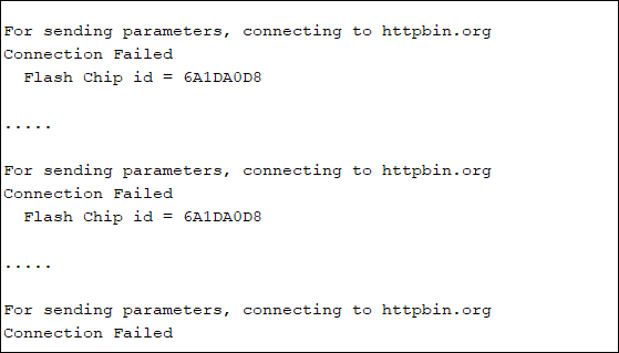
However, if you remove the client.setCACert() line from the setup, the connection will get established again securely, even with the faulty CA Certificate. This proves that setting the CA Certificate doesn't affect the security of our communication. It just helps us verify that we are communicating with the right server. If we do set the certificate, then the ESP32 won't communicate with the server unless the provided CA Certificate matches the server's CA Certificate. If we don't set the certificate, the ESP32 will still communicate with the server securely.
Congratulations!! You've successfully sent your HTTPS requests using ESP32.
Note − The hardware accelerator on ESP32 that performs the encryption of messages for HTTPS, can support a maximum of 16384 bytes (16 KB) of data. Therefore, if your message size exceeds 16 KB, you may need to break it down into chunks.
References
Transmitting data over WiFi using MQTT
MQTT (Message Queuing Telemetry Transport) has gained a lot of prominence in the context of IoT devices. It is a protocol that runs generally over TCP/IP. Instead of the server−client model that we saw for HTTP, MQTT uses the broker−client model. Wikipedia defines MQTT brokers and clients as −
An MQTT broker is a server that receives all messages from the clients and then routes the messages to the appropriate destination clients. An MQTT client is any device (from a micro controller up to a full−fledged server) that runs an MQTT library and connects to an MQTT broker over a network.
Think of the broker as a service like Medium. The topics would be the Medium publications, and the clients would be the Medium users. A user (client) can post to a publication, and another user (client) who has subscribed to that publication (topic) would be told that a new post is available for reading. By now, you would have understood a major difference between HTTP and MQTT. In HTTP, your messages are directly sent to the intended server and you even get an acknowledgment in the form of status codes. In MQTT, you just send messages to the broker in the hope that your intended server(s) will take it from there. Several features of MQTT turn out to be a boon if you are resource−constrained. They are listed below −
With MQTT, header overheads are very short and throughput is high. This helps save time and also battery.
MQTT sends information as a byte array instead of the text format. This makes the message lightweight.
Because MQTT isn't dependent on the response from the server, the client is independent and can go to sleep (conserve battery) as soon as it has transmitted the message.
These are just some of the points which have resulted in the popularity of MQTT. You can get a more detailed comparison between MQTT and HTTP here.
Code Walkthrough
In general, testing MQTT requires you to sign up for a free/ paid account with a broker. AWS IoT and Azure IoT are very popular platforms providing MQTT broker services, but they come with a lengthy signup and configuration process. Luckily, there is a free broker service from HiveMQ which can be used for testing MQTT without any signup or configuration. It is ideal for those of you who are new to MQTT and just want to get your hands dirty, and also lets you focus more on the firmware of ESP32. Therefore, that is the broker we will be using for this chapter. Of course, because it is a free service, there will be limitations. You can't share sensitive information, because all your messages are public, anyone can subscribe to your topics. For testing purposes, of course, these limitations won't matter.
The code can be found on GitHub
We will be using the PubSubClient library. You can install it from Tools −> Manage Libraries.
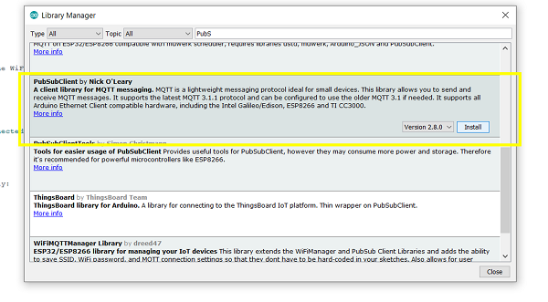
Once the library is installed, we include WiFi and PubSubClient libraries.
#include <WiFi.h>
#include <PubSubClient.h>
Next, we will define some constants. Remember to replace the WiFi credentials. The mqttServer and mqttPort are the once mandated by http://www.mqtt−dashboard.com/.The mqtt_client_name, mqtt_pub_topic and mqtt_sub_topic can be any strings of your choice. Just make sure that you do change their values. If multiple users copy the same code from this tutorial, you will receive a lot of messages from unknown clients when testing.
We also define the WiFiClient and mqttClient object. The MQTTClient object requires the network client as an argument. If you are using Ethernet, you would provide the Ethernet client as an argument. Since we are using WiFi, we have provided the WiFi client as an argument.
const char* ssid = "YOUR_SSID";
const char* password = "YOUR_PASSWORD";

//The broker and port are provided by http://www.mqtt−dashboard.com/
char *mqttServer = "broker.hivemq.com";
int mqttPort = 1883;

//Replace these 3 with the strings of your choice
const char* mqtt_client_name = "ESPYS2111";
const char* mqtt_pub_topic = "/ys/testpub"; //The topic to which our client will publish
const char* mqtt_sub_topic = "/ys/testsub"; //The topic to which our client will subscribe

WiFiClient client;
PubSubClient mqttClient(client);
Next, we define the callback function. A callback function is an interrupt function. Every time a new message is received from a subscribed topic, this function will be triggered. It has three arguments− the topic from which the message was received, the message as a byte array, and the length of the message. You can do whatever you want to do with that message (store it in SPIFFS, send it to another topic, and so on). Here, we are just printing the topic and the message.
void callback(char* topic, byte* payload, unsigned int length) {
   Serial.print("Message received from: "); Serial.println(topic);
   for (int i = 0; i < length; i++) {
      Serial.print((char)payload[i]);
   }
   Serial.println();
   Serial.println();
}
In the setup, we connect to the WiFi like in every other sketch. The last two lines concern MQTT. We set the server and port for MQTT and also the callback function.
void setup() {
   // put your setup code here, to run once:
   Serial.begin(115200);
   WiFi.mode(WIFI_STA);                    //The WiFi is in station mode
   WiFi.begin(ssid, password);
   while (WiFi.status() != WL_CONNECTED) {
      delay(500);
      Serial.print(".");
   }
   Serial.println("");  Serial.print("WiFi connected to: "); Serial.println(ssid);  Serial.println("IP address: ");     Serial.println(WiFi.localIP());
   delay(2000);
   mqttClient.setServer(mqttServer, mqttPort);
   mqttClient.setCallback(callback);
}
Within the loop, we do the following:
If the client is not connected to the broker, we connect it using our client name.
Once connected, we also subscribe our client to the mqtt_sub_topic.
We then publish a message to mqtt_pub_topic
We then run the mqttClient.loop(). This loop() function should be called regularly. It maintains the connection of the client with the broker and also helps the client process incoming messages. If you don't have this mqttClient.loop() line, you will be able to publish to mqtt_pub_topic, but won't get messages from mqtt_sub_topic, because the incoming messages are processed only when this line is called.
Finally, we wait for 5 seconds, before starting this cycle again.
void loop() {
   // put your main code here, to run repeatedly:
   if (!mqttClient.connected()){
      while (!mqttClient.connected()){
         if(mqttClient.connect(mqtt_client_name)){
            Serial.println("MQTT Connected!");
            mqttClient.subscribe(mqtt_sub_topic);
         }
         else{
            Serial.print(".");
         }
      }
   }
   mqttClient.publish(mqtt_pub_topic, "TestMsg");
   Serial.println("Message published");
   mqttClient.loop();
   delay(5000);
}
Testing the Code
In order to test the above code, you need to go to www.hivemq.com
Follow these steps once you are on that webpage −
Click Connect
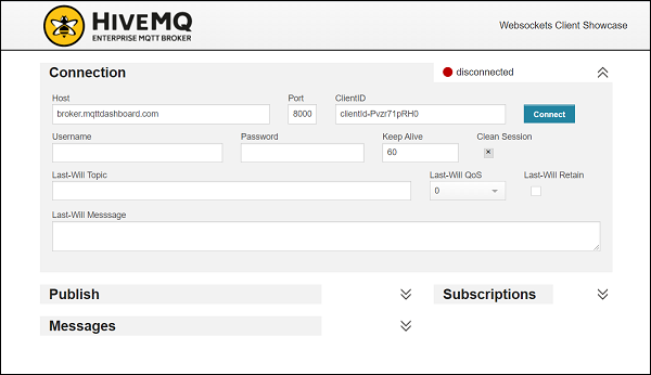
Click on Add New Topic Subscription and enter the name of the topic to which your ESP32 will publish (/ys/testpub in this case)
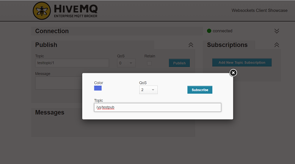
Once you flash your ESP32, you will start receiving messages on that topic every 5 seconds.
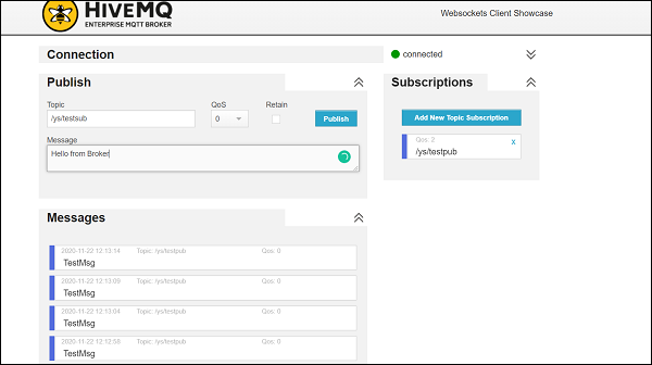
- Next, to test reception of message on ESP32, enter the name of the topic your ESP32 is subscribed to (ys/testsub in this case), then type a message in the message box and click publish. You should see the message on the Serial Monitor.
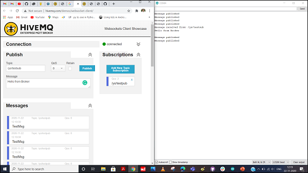
Congratulations!! You've tested both publish and subscribe using MQTT on ESP32.
References
Transmitting data over Bluetooth Classic
This chapter gives you an introduction to transmitting data over Bluetooth using ESP32. Arduino has a dedicated BluetoothSerial library for ESP32 that makes transmitting data over Bluetooth as simple as transmitting data to the Serial monitor. We will look at how to create a Bluetooth field around the ESP32, connect our smartphone to that field, and communicate with the ESP32.
Code Walkthrough
We will be using an example code for this chapter. You can find it in File −> Examples −> BluetoothSerial −>SerialToSerialBT. It can also be found on GitHub.
We begin with the inclusion of the BluetoothSerial library.
#include <BluetoothSerial.h>
The next few lines of code are a bit irrelevant if you haven't messed around with your ESP32. They check if Bluetooth is configured enabled, and throw up a warning if it is not. Bluetooth config is enabled by default on your ESP32, so you may as well comment out these lines if you have used your ESP32 strictly with the Arduino IDE. The make menuconfig which the error message refers to is actually accessed through ESP−IDF and not through Arduino IDE. So, the bottom line is, don't worry about these lines.
#if !defined(CONFIG_BT_ENABLED) || !defined(CONFIG_BLUEDROID_ENABLED)
#error Bluetooth is not enabled! Please run `make menuconfig` to and enable it
#endif
Next, we define the BluetoothSerial object.
BluetoothSerial SerialBT;
Within setup, we will begin the Bluetooth field around our ESP32 using the SerialBT.begin() function. This function takes an argument, the name of your Bluetooth device (ESP32 in this case). This is the name that will be shown when you scan for Bluetooth networks on your cell phone.
void setup() {
   Serial.begin(115200);
   SerialBT.begin("ESP32test"); //Bluetooth device name
   Serial.println("The device started, now you can pair it with bluetooth!");
}
Now, the loop is quite straightforward here. If you have any text coming in on Serial (i.e. text entered by you on the Serial Monitor), send it to over SerialBT. If you have any text coming in from the SerialBT, send it over Serial, or, in other words, print it on the Serial Monitor.
void loop() {
   if (Serial.available()) {
      SerialBT.write(Serial.read());
   }
   if (SerialBT.available()) {
      Serial.write(SerialBT.read());
   }
   delay(20);
}
Testing the code
To test this code, it is recommended that you download a Serial Bluetooth Terminal app (either the one shown below or any equivalent app) on your smartphone. It will help you pair with your ESP32, show you the messages received from ESP32, and also help you send messages to your ESP32.
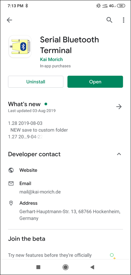
To install it on an Android device, click here. An equivalent app for iOS could be BluTerm.
You can find the screenshots of the tests performed with the Serial Bluetooth Terminal App below. I had changed the Bluetooth name of ESP32 to 'ESP32test345', because I had already paired my mobile phone with another ESP32 whose Bluetooth name was 'ESP32test'. Once the pairing is done, the device can be added in the Serial Bluetooth Terminal app, and you can then communicate with your device as if communicating with another user on a messaging app.
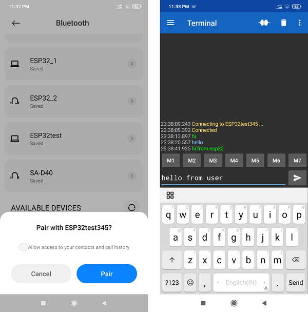
Pairing and Communication
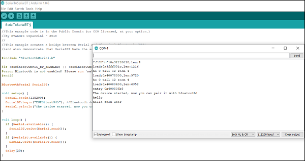
Corresponding view of Arduino Serial Terminal
Congratulations. You've communicated with your ESP32 using BlueTooth. Go ahead and explore the other examples that come along with the BluetoothSerial library.
Note − You may be tempted to use WiFi and Bluetooth simultaneously on ESP32. This is not recommended. While ESP32 has separate stacks for WiFi and Bluetooth, they share a common radio antenna. Therefore, the behavior of the module when both the stacks are trying to access the antenna becomes unpredictable. It is recommended that only one stack accesses the antenna at a time.
Getting current time from NTP Servers
In IoT devices, the timestamp becomes an important attribute of the packet exchanged between the device and the server. Therefore, it is necessary to have the correct time on your device at all times. One way is to use an RTC (Real Time Clock) interfaced with your ESP32. You can even use ESP32's internal RTC. Once given a reference time, it can correctly output future timestamps. But how will you get the reference time? One way is to hardcode the current time while programming the ESP32. But that is not a neat method. Secondly, the RTC is prone to drift and it is a good idea to keep providing it with reference timestamps regularly. In this chapter, we will see how to get the current time from NTP Servers, feed it to ESP32's internal RTC once, and print future timestamps.
A brief about NTP
NTP stands for Network Time Protocol. It is a protocol for clock synchronization between computer systems. In layperson terms, there is a server sitting somewhere which maintains time accurately. Whenever a client requests the current time from the NTP server, it sends back time accurate up to 100s of milliseconds. You can read more about NTP here. For ESP32, there is an in−built time library that handles all the communication with the NTP servers. Let's explore the use of that library in the code walkthrough below.
Code Walkthrough
We will use an in−built example for this walkthrough. It can be found in File −> Examples −> ESP32 −> Time −> SimpleTime. It can also be found on GitHub.
We begin with the inclusion of the WiFi and the time libraries.
#include <WiFi.h>
#include "time.h"
Next, we define some global variables. Replace the WiFi SSID and password with the corresponding values for your WiFi. Next, we have defined the URL for the NTP Server. The gmtOffset_sec refers to the offset in seconds of your timezone from the GMT or the closely related UTC. For instance, in India, where the timezone is 5 hours and 30 mins ahead of the UTC, the gmtOffset_sec will be (5+0.5)*3600 = 19800.
The daylightOffset_sec is relevant for countries that have daylight savings. It can simply be set to 0 in other countries.
const char* ssid       = "YOUR_SSID";
const char* password   = "YOUR_PASS";

const char* ntpServer = "pool.ntp.org";
const long  gmtOffset_sec = 3600;
const int   daylightOffset_sec = 3600;
Next, you can see a function printLocalTime(). It simply fetches the local time from the internal RTC and prints it to serial.
void printLocalTime()
{
   struct tm timeinfo;
   if(!getLocalTime(&timeinfo)){
      Serial.println("Failed to obtain time");
      return;
   }
   Serial.println(&timeinfo, "%A, %B %d %Y %H:%M:%S");
}
You might be having three questions here −
- Where is the struct tm defined?
- Where is the getLocalTime() function defined?
- What are the %A, %B, etc. formatters?
The struct tm is defined in the time.h file that we have included at the top. In fact, the time library is not an ESP32 specific library. It is an AVR library that is compatible to ESP32. You can find the source code at here. If you look at the time.h file, you will see the struct tm.
struct tm {
   int8_t   tm_sec; /**< seconds after the minute - [ 0 to 59 ] */
   int8_t   tm_min; /**< minutes after the hour - [ 0 to 59 ] */
   int8_t   tm_hour; /**< hours since midnight - [ 0 to 23 ] */
   int8_t   tm_mday; /**< day of the month - [ 1 to 31 ] */
   int8_t   tm_wday; /**< days since Sunday - [ 0 to 6 ] */
   int8_t   tm_mon; /**< months since January - [ 0 to 11 ] */
   int16_t  tm_year; /**< years since 1900 */
   int16_t  tm_yday; /**< days since January 1 - [ 0 to 365 ] */
   int16_t  tm_isdst; /**< Daylight Saving Time flag */
};
Now, the getLocalTime function is ESP32 specific. It is defined in the esp32−hal−time.c file. It is a part of the Arduino core for ESP32 and doesn't need a separate include in Arduino. You can see the source code here.
Now, the meaning of the formatters is given below −
/*
   %a Abbreviated weekday name
   %A Full weekday name
   %b Abbreviated month name
   %B Full month name
   %c Date and time representation for your locale
   %d Day of month as a decimal number (01−31)
   %H Hour in 24-hour format (00−23)
   %I Hour in 12-hour format (01−12)
   %j Day of year as decimal number (001−366)
   %m Month as decimal number (01−12)
   %M Minute as decimal number (00−59)
   %p Current locale's A.M./P.M. indicator for 12−hour clock
   %S Second as decimal number (00−59)
   %U Week of year as decimal number,  Sunday as first day of week (00−51)
   %w Weekday as decimal number (0−6; Sunday is 0)
   %W Week of year as decimal number, Monday as first day of week (00−51)
   %x Date representation for current locale
   %X Time representation for current locale
   %y Year without century, as decimal number (00−99)
   %Y Year with century, as decimal number
   %z %Z Time-zone name or abbreviation, (no characters if time zone is unknown)
   %% Percent sign
   You can include text literals (such as spaces and colons) to make a neater display or for padding between adjoining columns.
   You can suppress the display of leading zeroes  by using the "#" character  (%#d, %#H, %#I, %#j, %#m, %#M, %#S, %#U, %#w, %#W, %#y, %#Y)
*/
Thus, with our formatting scheme of %A, %B %d %Y %H:%M:%S, we can expect the output to be similar to the following: Sunday, November 15 2020 14:51:30.
Now, coming to the setup and the loop. In the setup, we initialize Serial, connect to the internet using our WiFi, and configure the internal RTC of ESP32 using the configTime() function. As you can see, that function takes in three arguments, the gmtOffset, the daylightOffset and the ntpServer. It will fetch the time from ntpServer in UTC, apply the gmtOffset and the daylightOffset locally, and return the output time. This function, like getLocalTime, is defined in the esp32-hal-time.c file. As you can see from the file, TCP/IP protocol is used for fetching time from the NTP server.
Once we've obtained the time from the NTP server and fed it to the internal RTC of the ESP32, we no longer need WiFi. Thus, We disconnect the WiFi and keep printing time in the loop every second. You can see on the serial monitor that the time gets incremented by one second in every print. This is because the internal RTC of ESP32 maintains the time once it got the reference.
void setup()
{
   Serial.begin(115200);

   //connect to WiFi
   Serial.printf("Connecting to %s ", ssid);
   WiFi.begin(ssid, password);
   while (WiFi.status() != WL_CONNECTED) {
      delay(500);
      Serial.print(".");
   }
   Serial.println(" CONNECTED");

   //init and get the time
   configTime(gmtOffset_sec, daylightOffset_sec, ntpServer);
   printLocalTime();

   //disconnect WiFi as it's no longer needed
   WiFi.disconnect(true);
   WiFi.mode(WIFI_OFF);
}
void loop() {
  delay(1000);
  printLocalTime();
}
The Serial Monitor output will look like −
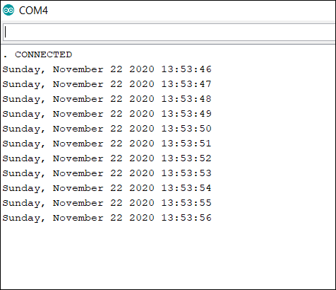
That's it. You've learned how to get the correct time from the NTP servers and configure your ESP32's internal RTC. Now, in whatever packets you send to the server, you can add the timestamp.
References
Performing Over-The-Air Update of ESP32 firmware
Say you have a thousand IoT devices out in the field. Now, if one fine day, you find a bug in the production code, and wish to fix it, will you recall all the thousand devices and flash the new firmware in them? Probably not! What you'll prefer to have is a way to update all the devices remotely, over-the-air. OTA updates are very common these days. Every now and then, you keep receiving software updates to your Android or iOS smartphones. Just like software updates can happen remotely, so can firmware updates. In this chapter, we will look at how to update the firmware of ESP32 remotely.
OTA Update Process
The process is quite simple. The device first downloads the new firmware in chunks and stores it in a separate area of the memory. Let's call this area the 'OTA space'. Let's call the area of the memory where the current code or the application code is stored as the 'Application space'. Once the entire firmware has been downloaded and verified, the device bootloader swings into action. Consider the bootloader as a code written in a separate area of the memory (let's call it the 'Bootloader space'), whose sole purpose is to load the correct code in the Application space every time the device restarts.
Thus, every time the device restarts, the code in the Bootloader space gets executed first. Most of the time, it simply passes control to the code in the Application space. However, after downloading the newer firmware, when the device restarts, the bootloader will notice that a newer application code is available. So it will flash that newer code from the OTA space into the Application space and then give control to the code in the Application space. The result will be that the device firmware will be upgraded.
Now, digressing a bit, the bootloader can also flash the factory reset code from the 'Factory Reset space' to the Application space, if the Application code is corrupted, or a factory reset command is sent. Also, often, the OTA code and the factory reset codes are stored on external storage devices like an SD Card or an external EEPROM or FLASH chip, if the microcontroller doesn't have enough space. However, in the case of ESP32, the OTA code can be stored in the microcontroller's memory itself.
Code Walkthrough
We will be using an example code for this chapter. You can find it in File −> Examples −> Update −> AWS_S3_OTA_Update. It can also be found on GitHub.
This is one of the very detailed examples available for ESP32 on Arduino. The author of this sketch has even provided the expected Serial Monitor output of the sketch in comments. So while much of the code will be self−explanatory through the comments, we'll walk over the broad idea and also cover the important details. This code makes use of the Update library which, like many other libraries, makes working with ESP32 very easy, while keeping the rigorous work under−the−hood.
In this specific example, the author has kept the binary file of the new firmware in an AWS S3 bucket. Providing a detailed overview of AWS S3 is beyond the scope of this chapter, but very broadly, S3 (Simple Storage Service) is a cloud storage service provided by Amazon Web Services (AWS). Think of it like Google Drive. You upload files to your drive and share a link with people to share it. Similarly, you can upload a file to S3 and access it via a link. S3 is much more popular because a lot of other AWS services can interface seamlessly with it. Getting started with AWS S3 will be easy. You can get help from several resources available through a quick Google search. In the comments at the beginning of the sketch as well, a few steps to get started are mentioned.
An important recommendation to note is that you should use your own binary file for this code. The comments at the top of the sketch suggest that you can use the same binary file that the author has used. However, downloading a binary compiled on another machine/ another version of Arduino IDE has been known to cause errors sometimes in the OTA process. Also, using your own binary will make your learning more 'complete'. You can export the binary of any ESP32 sketch by going to Sketch −> Export Compiled Binary. The binary (.bin) file gets saved in the same folder in which your Arduino (.ino) file is saved.
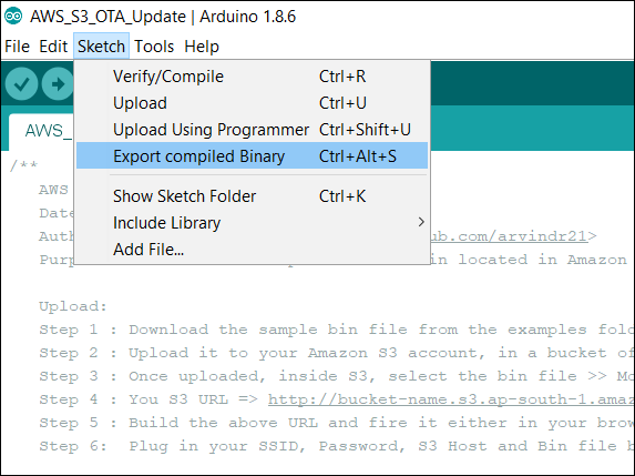
Once your binary is saved, you just need to upload it to S3 and add the link to the bucket and address of the binary file in your code. The binary you save should have some print statement to indicate that it is different from the code you flash in the ESP32. A statement like "Hello from S3" maybe. Also, don't keep the S3 bucket link and bin address in the code as it is.
Alright! Enough talk! Let's begin the walkthrough now. We will begin by including the WiFi and Update libraries.
#include <WiFi.h>
#include <Update.h>
Next, we define a few variables, constants, and also the WiFiClient object. Remember to add your own WiFi credentials and S3 credentials.
WiFiClient client;

// Variables to validate
// response from S3
long contentLength = 0;
bool isValidContentType = false;

// Your SSID and PSWD that the chip needs
// to connect to
const char* SSID = "YOUR−SSID";
const char* PSWD = "YOUR−SSID−PSWD";

// S3 Bucket Config
String host = "bucket−name.s3.ap−south−1.amazonaws.com"; // Host => bucket−name.s3.region.amazonaws.com
int port = 80; // Non https. For HTTPS 443. As of today, HTTPS doesn't work.
String bin = "/sketch−name.ino.bin"; // bin file name with a slash in front.
Next, a helper function getHeaderValue() has been defined, which basically is used to check the value of a particular header. For example, if we get the header "Content-Length: 40" and it is stored in a String called headers, getHeaderValue(headers,"Content−Length: ") will return 40.
// Utility to extract header value from headers
String getHeaderValue(String header, String headerName) {
   return header.substring(strlen(headerName.c_str()));
}
Next, the main function execOTA(), which performs the OTA. This function has the entire logic related to the OTA. If you look at the Setup, we simply connect to the WiFi and call the execOTA() function.
void setup() {
   //Begin Serial
   Serial.begin(115200);
   delay(10);

   Serial.println("Connecting to " + String(SSID));

   // Connect to provided SSID and PSWD
   WiFi.begin(SSID, PSWD);

   // Wait for connection to establish
   while (WiFi.status() != WL_CONNECTED) {
      Serial.print("."); // Keep the serial monitor lit!
      delay(500);
   }

   // Connection Succeed
   Serial.println("");
   Serial.println("Connected to " + String(SSID));

   // Execute OTA Update
   execOTA();
}
So you would have understood that understanding the execOTA function means understanding this entire code. Therefore, let's begin the walkthrough of that function.
We begin by connecting to our host, which is the S3 bucket in this case. Once connected, we fetch the bin file from the bucket, using a GET request (refer to the HTTP tutorial for more information on GET requests)
void execOTA() {
   Serial.println("Connecting to: " + String(host));
   // Connect to S3
   if (client.connect(host.c_str(), port)) {
   // Connection Succeed.
   // Fecthing the bin
   Serial.println("Fetching Bin: " + String(bin));

   // Get the contents of the bin file
   client.print(String("GET ") + bin + " HTTP/1.1\r\n" +
      "Host: " + host + "\r\n" +
      "Cache-Control: no-cache\r\n" +
      "Connection: close\r\n\r\n");
Next, we wait for the client to get connected. We give a maximum of 5 seconds for the connection to get established, otherwise we say that the connection has timed out and return.
unsigned long timeout = millis();
while (client.available() == 0) {
   if (millis() - timeout > 5000) {
      Serial.println("Client Timeout !");
      client.stop();
      return;
   }
}
Assuming that the code has not returned in the previous step, we have a successful connection established. The expected response from the server is provided in the comments. We begin by parsing that response. The response is read line by line, and each new line is stored in a variable called line. We specifically check for the following 3 things −
If the response status code is 200 (OK)
What is the Content-Length
Whether the content type is application/octet-stream (this is the type expected for a binary file)
The first and third are required, and the second is just for information.
while (client.available()) {
   // read line till /n
   String line = client.readStringUntil('\n');
   // remove space, to check if the line is end of headers
   line.trim();

   // if the the line is empty,
   // this is end of headers
   // break the while and feed the
   // remaining `client` to the
   // Update.writeStream();
   if (!line.length()) {
   //headers ended
   break; // and get the OTA started
   }

   // Check if the HTTP Response is 200
   // else break and Exit Update
   if (line.startsWith("HTTP/1.1")) {
      if (line.indexOf("200") < 0) {
         Serial.println("Got a non 200 status code from server. Exiting OTA Update.");
         break;
      }
   }

   // extract headers here
   // Start with content length
   if (line.startsWith("Content-Length: ")) {
      contentLength = atol((getHeaderValue(line, "Content-Length: ")).c_str());
      Serial.println("Got " + String(contentLength) + " bytes from server");
   }

   // Next, the content type
   if (line.startsWith("Content-Type: ")) {
      String contentType = getHeaderValue(line, "Content-Type: ");
      Serial.println("Got " + contentType + " payload.");
      if (contentType == "application/octet-stream") {
         isValidContentType = true;
      }
   }
}
With this, the if block that checks if the connection with the server was successful ends. It is followed by the else block, which just prints that we were unable to establish connection to the server.
} else {
   // Connect to S3 failed
   // May be try?
   // Probably a choppy network?
   Serial.println("Connection to " + String(host) + " failed. Please check your setup");
   // retry??
   // execOTA();
}
Next, if we have hopefully received the correct response from the server, we will have a positive contentLength (remember, we had initialized it with 0 at the top and so it will still be 0 if we somehow did not reach that line where we parse the Content−Length header). Also, we will have isValidContentType as true (remember, we had initialized it with false). So we check if both of these conditions are true and if yes, proceed with the actual OTA. Note that so far, we have only made use of the WiFi library, for interacting with the server. Now if the server interaction turns out to be alright, we will begin use of the Update library, otherwise, we simply print that there was no content in the server response and flush the client. If the response was indeed correct, we first check if there is enough space in the memory to store the OTA file. By default, about 1.2 MB of space is reserved for the OTA file. So if the contentLength exceeds that, Update.begin() will return false. This 1.2MB number can change depending on the partitions of your ESP32.
// check contentLength and content type
if (contentLength && isValidContentType) {
   // Check if there is enough to OTA Update
   bool canBegin = Update.begin(contentLength);
Now, if we indeed have space to store the OTA file in memory, we begin writing the bytes to the memory area reserved for OTA (the OTA space), using the Update.writeStream() function. If we don't, we simply print that message and flush the client, and exit the OTA process. The Update.writeStream() function returns the number of bytes that were written to the OTA space. We then check if the number of bytes written is equal to the contentLength. If the Update is completed, in which case the Update.end() function will return true, we check if it has finished properly, i.e. all bytes are written, using the Update.isFinished() function. If it returns true, meaning that all bytes have been written, we restart the ESP32, so that the bootloader can flash the new code from the OTA space to the Application space, and our firmware gets upgraded. If it returns false, we print the error received.
   // If yes, begin
   if (canBegin) {
      Serial.println("Begin OTA. This may take 2 − 5 mins to complete. Things might be quite for a while.. Patience!");
      // No activity would appear on the Serial monitor
      // So be patient. This may take 2 - 5mins to complete
      size_t written = Update.writeStream(client);

      if (written == contentLength) {
         Serial.println("Written : " + String(written) + " successfully");
      } else {
         Serial.println("Written only : " + String(written) + "/" + String(contentLength) + ". Retry?" );
         // retry??
         // execOTA();
      }

      if (Update.end()) {
         Serial.println("OTA done!");
         if (Update.isFinished()) {
            Serial.println("Update successfully completed. Rebooting.");
            ESP.restart();
         } else {
            Serial.println("Update not finished? Something went wrong!");
         }
      } else {
         Serial.println("Error Occurred. Error #: " + String(Update.getError()));
      }
   } else {
      // not enough space to begin OTA
      // Understand the partitions and
      // space availability
      Serial.println("Not enough space to begin OTA");
      client.flush();
   }
}
Of course, you would have realized by now that we need not do anything in the loop here.
That's it. You've successfully upgraded the firmware of your ESP32 chip remotely. If you are more curious about what each function of the Update library does, you can refer to the comments in the Update.h file.
References
Applications of ESP32
Now that you are fairly familiar with ESP32, let's look at its application. This is a chapter where I feel I need not tell you much. After going through the various chapters in this tutorial, you would have started forming ideas in your head. You would have already created a rough list of applications where you could use ESP32. And the good news is that most of the applications you've listed are feasible.
However, ESP32 is more feasible for some applications than others. In this chapter, my focus will be on making you understand the factors you should consider when deciding whether to use ESP32 for an application or not. Please note that this chapter is production focused, i.e., when we are talking of a scale of thousands or lakhs of devices. If you have a requirement of a handful of devices and ESP32 can serve them, just simply go ahead and use ESP32 without a second thought. Also, for prototyping/ establishing Proof of Concept (PoC), you can use ESP32 without any hesitation.
One of the major advantages of ESP32 is the presence of inbuilt WiFi and Bluetooth stacks and hardware. Therefore, ESP32 will be your choice of microcontroller in a static application where good WiFi connectivity is guaranteed, say an environment monitoring application in, say, a laboratory. The presence of WiFi stack on the module itself means you will have saved money on an additional networking module. However, if you use ESP32 in an asset tracking application, where it keeps moving around, you will have to rely on a GSM or LTE module for connectivity to the server (because you will not be guaranteed WiFi availability). In such a scenario, ESP32 loses the competitive advantage, and you may be better off using a cheaper microcontroller that can serve your purpose.
On similar lines, having a hardware accelerator for encrypting messages makes ESP32 ideal for applications requiring secure communication (HTTPS). So if you are dealing with sensitive information that you don't want to fall in the wrong hands, using ESP32 is advantageous over other microcontrollers that don't support encryption. An example application can be Industrial IoT in the defense sector.
The presence of two cores again makes ESP32 your choice of microcontroller for processing-heavy applications like those receiving data at a very high baud rate and requiring the data processing and transmission to run on separate cores. Several such applications can be found in Industrial IoT. But for a very light application, where you don't even require secure communication, a microcontroller having modest specs may prove to be more useful. After all, what is the use of having (and effectively paying for) two cores, when you can make do with one?
Another factor to consider is the number of GPIOs and peripherals. ESP32 has 3 UART channels. If you have an application where you need more than 3 UART channels, you may have to look for another microcontroller. Similarly, ESP32 has 34 programmable GPIOs which are more than sufficient for most applications. However, if your application does require more GPIOs, you may have to switch to another microcontroller
ESP32's 1.5 MB of default SPIFFS provides you with more storage onboard the microcontroller than most other microcontrollers. If your storage requirements are within 1.5 MB, ESP32 saves you the cost of an external SD Card or Flash Chip. ESP32 does wear-leveling within SPIFFS by itself, saving you a lot of development efforts as well. However, if your storage requirements are not met by ESP32, again, the competitive advantage disappears.
ESP32's 520 KB of RAM is also more than sufficient for most applications. It is only for very heavy applications like image/video processing where this proves to be a bottleneck.
To summarize, ESP32 has specs that are good enough to accommodate most of your applications. When scaling up production, you need to just make sure that the specs are not an overkill for you. In other words, if you can get the desired output with modest specs, you may be better off using a cheaper microcontroller and save money. These savings become significant when your production numbers increase by orders of magnitude. However, production aside, ESP32 is definitely the ideal microcontroller for prototyping and establishing the PoC.
Next steps for you as a developer
If you have made it so far, congratulations! You are at a stage where you are not only familiar with ESP32 but also have enough know-how to explore it further. And there is indeed a lot more to explore. Several cool applications can be realized if you know some additional concepts. In this chapter, I'll just be giving you directions for this exploration. In fact, it will be much better if I just list them down. Given below is the non−exhaustive list of topics/ areas which you can explore further, and concepts which you can learn about:
Firmware
Sleep modes − You will require to know these in applications which have a scarcity of power
Timers − For scheduled tasks
Interrupts − For tasks triggered by an asynchronous event
Watchdog Timeout − Reset your microcontroller if it is stuck somewhere for too long
Mutex and Semaphore (RTOS related) − When multiple threads want to access a shared resource
Adjusting the partitions of ESP32 for providing more space to SPIFFS
Sensor Interface
Touch Sensors with ESP32
Hall Sensor with ESP32
GNSS receiver with ESP32 (almost all IoT devices have a GNSS receiver for getting location information)
Network Related
BLE (Bluetooth Low Energy) with ESP32
Connecting ESP32 to an external Bluetooth field
WiFi in Access Point (AP) with ESP32
ESP32 as a web server
Captive portal using ESP32 (in restaurants or airports, the screen that pops up as soon as you connect to the WiFi, prompting you for your mobile number, that is called the Captive Portal)
Data transfer using UDP
Data transfer using TCP
DNS Server
Data transfer over LoRa
MQTT with brokers on AWS/ Azure
Peripheral connectivity
CAN protocol (used for automotive applications)
I2C and SPI with multiple slaves
Interface of SD Card with ESP32
One wire protocol
Data processing
FFT on ESP32
Power calculations (RMS value, Peak to Peak, power factor, etc.)
Don't get overwhelmed by looking at the above list. You don't have to learn everything in a day. Nor are you required to learn everything. As mentioned in the beginning, the above list just provides you with directions for further exploration. You can choose topics that suit your application. For all the topics where you have an example code available, there is no better place to get started. For others, you can read the documentation of the available libraries related to those topics, go through their .h files, and browse through the internet for examples. With such a massive online community, it is very difficult to not find help online. So, keep learning and keep exploring .