- TSSN - Home
- TSSN - Introduction
- TSSN - Switching Systems
- Elements of a Switching System
- TSSN - Strowger Switching System
- TSSN - Switching Mechanisms
- TSSN - Common Control
- TSSN - Touch-tone Dial Telephone
- TSSN - Crossbar Switching
- Crossbar Switch Configurations
- TSSN - Crosspoint Technology
- TSSN - Stored Program Control
- TSSN - Software Architecture
- TSSN - Switching Techniques
- TSSN - Time Division Switching
- TSSN - Telephone Networks
- TSSN - Signaling Techniques
- TSSN - ISDN
TSSN - Touch-tone Dial Telephone
In this chapter, we will learn about the Touch-tone Dial Telephone technology. When we talk about the technological development of the telephone set, the rotary dial was used in the initial stages. Slower dialing was one major disadvantage associated with the Rotary dial. It took 12 seconds to dial a 7-digit number on a Rotary dial. The step-by-step switching elements of the Strowger switching system, cannot respond to rates higher than 10-12 pulses per second.
It uses the DTMF technology, prior to which the pulse dialing technique was used. In the Pulse dialing technique which is also called a Loop disconnect technique, repeated connecting and disconnecting of the lines is done, like clicks of a switch; this is interpreted by the exchange as the number dialed, according to the number of clicks.
Need for Touch-tone
With the introduction of the Common Control subsystems into switching exchanges, there came the feasibility for higher rates of dialing. Hence, a new system called the Touch-tone dialing was developed in Telephony to replace the Rotary dial; this was considered to benefit the customer with higher speed. This has also removed the disadvantages of limited usage and limited signaling capacity along with lower speed.
The Pulse dialing is limited to signaling between the exchange and the subscriber, but not between two subscribers, which is called End-to-End signalling. End-to-End signaling is a desirable feature and is possible only if the signaling is in voice frequency band so that the signaling information can be transmitted to any point in the telephone network to which voice can be transmitted.
Hence replacing the inconvenience of using the rotary dial, the touch-tone dial telephone was introduced. The development of the touch-tone dial telephone came around 1950. However, the usage of it started somewhere around 1964. The following figure shows a practical touch-tone dial telephone.
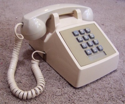
The above figure will help you understand that the rotary dial is replaced with a push button keyboard, where the buttons, if touched to press the button will generate frequencies related to the number dialed. The hassle-free rotation was replaced and a feature to redial the number was added to this push button keyboard, where the dialed number is stored until another number is dialed. This eased the process of redialing a 7- digit number all over again.
How does the Touch-tone Dial Telephone Operate?
The press of a button on the touch-tone dial telephone indicates the number dialed using certain frequencies. Touching or light pressing of a number generates a tone which is a combination of two frequencies, one from lower band and the other from upper band.
For example, by pressing the button 9, two frequencies such as 852 Hz the lower frequency and 1477Hz the upper frequency are produced. The design of touch-tone dialing producing two frequencies is as shown below.
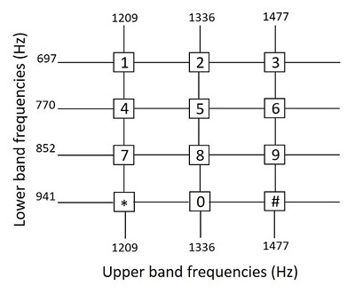
The DTMF (Dual-tone Multi-frequency) dialing can be done through the touch-tone dialing technique as shown above. As two frequencies, one being higher and the other being lower are transmitted at the same time in the touch-tone dialing technique, it is called the Dual-tone Multi Frequency (DTMF) dialing. The two signals produced are for a duration of 100ms, which are selected by the key pressed from the matrix as shown above. Each key is uniquely referenced by selecting one of the four lower band frequencies associated with the matrix rows, coupled with selecting one of the three higher band frequencies associated with the matrix column.
Design Considerations
The design considerations are
- Choice of Code
- Band Separation
- Choice of Frequencies
- Choice of Power Levels
- Signaling Duration
The choice of code for touch-tone signaling should be such that the imitation of code signals by music and speech must be difficult.
Consider the following reasons for separating the band of two frequencies −
At the receiver, band filtering is used to separate the frequency groups; this helps to determine the specific frequencies in a simple way.
Easy amplitude regulation of each frequency component separately.
Limiters can be used to guard the action of each frequency separately.
The probability of false response is reduced.
The attenuation and delay distortion characteristics of the telephone network circuits determine the choice of frequencies. A flat amplitude response with a very low attenuation and a uniform delay response with a low relative delay value are desirable. Though the design is high enough for reliability, the choice of power levels should be planned according to attenuation characteristics of the channel. The signal duration although inefficient is longer and helpful to combat talk-off.
Internal Mechanism
The internal mechanism of the touch-tone receiver can be explained by a simple block diagram which contains Band Separation Filter (BSF), Limiters (L), Selector Circuits (S) and Detectors (D) which give out Low Band Frequency (LBF) signals and High Band Frequency (HBF) signals, as indicated below.
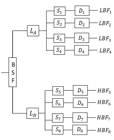
The Band separation filter present at the receiver is used to separate the frequency groups. This helps to determine the specific frequencies, separately. In addition, the filter also regulates the amplitudes of each component. Then the signal reaches the limiter, which has two of the frequencies at its input. It allows the dominant signal through it bypassing the weak signal. If both of the signals have the same strength, the limiter output is much below the full output and neither of the signal dominates.
The selectors present in the circuitry, are designed to recognize the signal when it falls within the specified narrow passband and has an amplitude within the range of 2.5dB of full output of the limiter. Both of the limiter and selector circuits are efficient in recognizing the difference between the touch-tone and the voice signal, to avoid talk-off. For further improvement, Band Elimination filters are sometimes used in place of Band Separation filters as they permit a wide spectrum of speech to pass through the filters. The high and low band frequency signals reach the output separately through the detector outputs.