- TSSN - Home
- TSSN - Introduction
- TSSN - Switching Systems
- Elements of a Switching System
- TSSN - Strowger Switching System
- TSSN - Switching Mechanisms
- TSSN - Common Control
- TSSN - Touch-tone Dial Telephone
- TSSN - Crossbar Switching
- Crossbar Switch Configurations
- TSSN - Crosspoint Technology
- TSSN - Stored Program Control
- TSSN - Software Architecture
- TSSN - Switching Techniques
- TSSN - Time Division Switching
- TSSN - Telephone Networks
- TSSN - Signaling Techniques
- TSSN - ISDN
TSSN - Signaling Techniques
Signaling techniques enable the circuit to function as a whole by inter connecting all varieties of switching systems. There are three forms of signaling involved in a telecommunication network.
- Subscriber loop signaling
- Intraexchange or register signaling
- Interexchange or inter-register signaling
The subscriber loop signaling depends upon the type of telephone instrument used. The intra exchange signaling refers to the internal portion of a switching system that is heavily dependent upon the type and design of a switching system, which varies depending upon the model. The inter-exchange signaling takes place between exchanges. This helps in the exchange of address digits, which pass from exchange to exchange on a link-by-link basis. The network-wide signaling that involves end-to-end signaling between the originating exchange and the terminating exchange is called the Line signaling.
The two main types of signaling techniques are −
In-Channel Signaling
In-Channel Signaling is also known as Per Trunk Signaling. This uses the same channel, which carries user voice or data to pass control signals related to that call or connection. No additional transmission facilities are needed, for In-channel signaling.
Common Channel Signaling
Common Channel Signaling uses a separate common channel for passing control signals for a group of trunks or information paths. This signaling does not use the speech or the data path for signaling.
We will discuss the signaling techniques in depth in our subsequent sections.
Types of Signaling Techniques
As discussed above, the signaling techniques are categorized into two, the In-channel signaling and the Common channel signaling. However, these are further divided into few types depending upon the frequencies and frequency techniques used.
The division is as shown in the following figure −
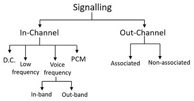
In-channel Signaling
This type of signaling is used to carry voice or data and pass control signals related to a call or connection. There are different types of In-channel Signaling, as seen in the above figure. The D.C. signaling is simple, cheap and reliable even for unamplified audio circuits. However, for amplified audio circuits, low frequency A.C. signaling may be adopted.
The Voice Frequency signaling is used when FDM (Frequency Division Multiplexing) transmission systems are used, because low frequency signaling and D.C. signaling cannot be provided. This Voice Frequency signaling may be In-band or Out-band.
In-band Signaling
In-band voice frequency uses the same frequency band as the voice, which is 300-3400 Hz, which has to be protected against false operation by speech. One such instant took place when a ladys voice which has generated a tone at around 2600Hz lasting for a duration of 100ms was detected as the line disconnect signal due to which her calls were frequently being disconnected in the middle of her conversation. Such problems precluded the in-band signaling during speech phase.
The advantages of In-band signaling are −
The control signals can be sent to every part where a speech signal can reach.
The control signals will be independent of the transmission systems as they are carried along with the speech signals.
The Analog to digital and Digital to analog conversion processes will not affect them.
Out-band Signaling
The out-band signaling uses frequencies which are above the voice band but below the upper limit of 4000 Hz of the nominal voice channel spacing. The signaling is done throughout the speech period and thus continuous supervision of the call is allowed. Extra circuits are needed to handle the extremely narrow band width of this signaling, due to which it is seldom used. Both of these in-band and out-band voice frequency signaling techniques have limited information transmission capacity. In order to provide enhanced facilities, common channel signaling is used.
Common Channel Signaling
Common Channel Signaling uses a separate common channel for passing control signals for a group of trunks or information paths as it does not use the speech or the data path for signaling. The common channel signaling consists of two types of nodes such as Signaling Transfer Points (STP) and Signaling Points (SP).
A Signaling point is capable of handling control messages directly addressed to it but is incapable of routing messages. Signaling transfer point is capable of routing messages and can perform the functions of SP.
This common channel signaling is implemented in two modes −
- Channel associated mode
- Channel non-associated mode
Channel-associated Mode
In the channel-associated mode, the channel closely tracks the trunk groups along the entire length of the connection. Here, the signaling is done on a separate channel; the signaling path passes through the same set of switches, as does the speech path.
The following figure shows the associated mode of operation in common channel signalling

The signaling paths for the speech paths A-B, A-C-B and B-D are A-B, A-C-B and B-D respectively. The advantages of this signaling are −
The implementation is economic
The assignment of trunk groups is simple
Channel Non-associated Mode
In the channel non-associated mode, there is no close or simple assignment of the control channels to trunk groups. It follows a different path from that of the speech signal as shown in the following figure.
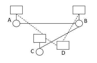
The signaling paths for the speech paths A-B and B-C are A-C-D-B and B-D-C respectively. The network topologies are different for signaling and speech networks. Though this scheme offers flexibility as there is no switching center, it is a bit complex, as the signal messages may be transferred between the two end switching systems via any available path in the common channel signaling network according to its own routing principles.
Private Branch Exchange (PBX)
Private Branch Exchange or PBX can be understood as a local exchange within an office or a building, in order to communicate within themselves. As the name implies, it is a private exchange, which is a branch to the main exchange similar to a local loop connected to the main loop as a branch.
Private Branch Exchange is a telephone system within a local area that switches calls between those users on local lines while allowing all users to share a certain number of external phone lines. The main purpose of PBX is to save the cost of requirement for a line to each user to the central exchange office.
The following figure shows the model of a PBX.
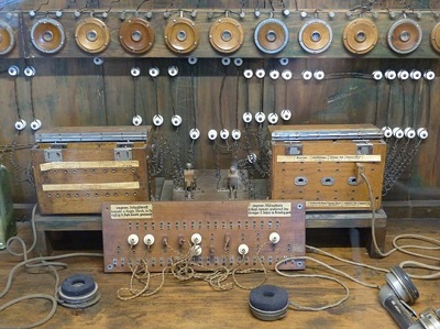
The above figure shows an early model of the PBX system. The PBX is usually operated and owned by the local office where the users are connected through it within that limited area.
The parts of a PBX include −
A telephone trunk that contains many phone lines, which are terminated at PBX.
A computer that handles the incoming and outgoing calls of PBX along with switching between different calls within the local loop.
The network of lines within the PBX.
A human operator console, which is optional.
Having all these along with the PBX equipment, the local branch exchange is built. The PBX exchanges previously operated using the analog technology. However, these exchanges operate on digital technology. The digital signals are converted to analog for outside calls on the local loop using Plain Old Telephone Services (POTS).