- TSSN - Home
- TSSN - Introduction
- TSSN - Switching Systems
- Elements of a Switching System
- TSSN - Strowger Switching System
- TSSN - Switching Mechanisms
- TSSN - Common Control
- TSSN - Touch-tone Dial Telephone
- TSSN - Crossbar Switching
- Crossbar Switch Configurations
- TSSN - Crosspoint Technology
- TSSN - Stored Program Control
- TSSN - Software Architecture
- TSSN - Switching Techniques
- TSSN - Time Division Switching
- TSSN - Telephone Networks
- TSSN - Signaling Techniques
- TSSN - ISDN
TSSN - Quick Guide
TSSN - Introduction
The world has undergone many changes since the evolution of man. For instance, the exchange of information was initially in the form of signs and sounds. This transitioned to the language and script form with advanced inventions. The communication from one place to another which called for distance between individuals was carried through letters; sent by pigeons and between two groups through drum beats or semaphores. Men used to travel long distances to pass on messages.
Todays world is more an age of communication. The advancement of communication techniques has increased the speed with which the transfer of information takes place. This development has not been an easy process. At the onset of the invention of communication systems, the invention and usage of telephony was the most important one. The way the telephone systems evolved from a basic system into an essential multi-purpose friendly gadget today, leaves one and all astonished knowing the innovations made out of the meagre resources available in those days.
Telecommunications
The exchange of information between two or many individuals is called Communication. The word tele is a Greek word which means distance. Hence, Telecommunication means the exchange of information between two distant places.
Telecommunications represent the transfer of information, from an entity at one place to an entity at another place, whereas the information can be in the form of data, voice or symbol. The entities can be human beings, computers, facsimile machines, telegraphy machines, phones or so on. In telephone conversation, the one who initiates the call is referred to as the Calling Subscriber and the one for whom the call is destined is the Called Subscriber. In other cases of information transfer, the communicating entities are known as Source and Destination, respectively.
In March 1876, Alexander Graham Bell invented and demonstrated his telephone set and the possibility of long distance voice communication. He demonstrated the point-to-point communication, in which a calling subscriber chooses the appropriate link to establish connection with the called subscriber. This system also requires some mode of Signalling to alert the called subscriber about the incoming call and a signal to indicate the calling subscriber, when the called subscriber is busy on another call.
Need for Switching Exchanges
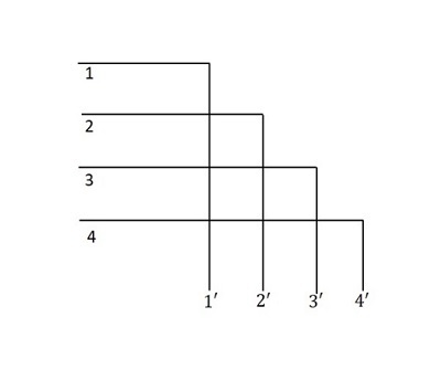
The point-to-point connection for establishing communication requires the telephone sets to be linked using wires. If the number of telephone sets or the subscribers present is low in number, the type of connection will be a little complex. However, if this number is high or moderate, then the connections will lead to a mess. To understand the complication, let us consider a network of 5 subscribers.
The following illustration shows a point-to-point connection for five subscribers (telephone sets):
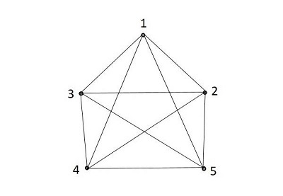
In the point-to-point connection, for n entities, we need n(n-1)/2 links. All these links form a network. Networks with point-to-point links among all the entities are known as Fully Connected Networks. The number of links required in a fully connected network becomes very large even with moderate values of n.
Hence, a system of switching the networks is needed in-between these subscribers. Alexander Graham Bell recommended the Switching between the subscribers using a switching office that maintains the telephone connections.
Switching Systems
This network connection cannot be simply made with telephone sets and bunch of wires, but a good system is required to make or break a connection. This system is known as the Switching System or the Switching Office or the Exchange. With the introduction of the switching system, the subscribers instead of getting connected directly to one another, are connected to a switching office and then to the required subscriber.
The following figure will help you understand the switching system.
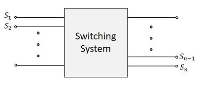
With the introduction of switching systems, the need for traditional connections between the subscribers reduced. All the subscribers need to have a connection with the switching system, which makes or breaks any connection, requested by the calling subscriber. The switching system, which is also called the Telephone Exchange, takes care of establishing the calls. Hence, the total number of such links is equal to the number of subscribers connected to the system.
Signaling is required for the switching system to establish or release a connection. It should also enable the switching system to detect whether a called subscriber is busy and if so, indicate the same to the called subscriber. The functions performed by a switching system in establishing and releasing connections are known as Control Functions.
The early systems required manual operations to establish telephone calls. An operator used to receive a call from the calling subscriber and then connect the call to the called subscriber. Later on, the system was automated.
Telephone Model
The following figure will help you understand the model of telephones in the early stage of its invention.
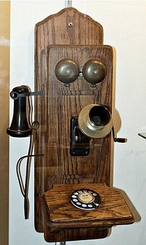
When you see the telephone in the above figure, the dialer part and the microphone are connected to a stationary wooden plank; and the speaker to listen, was connected by awire at the side. The top portion of the telephone has two bells connected - these bells ring when there is an incoming call. This is one of the earlier models of the telephone.
The telephone sets of the calling subscriber and the called subscriber are connected through a switching system or a telephone exchange in order to establish the calls requested.
In the following sections, we will learn about the switching system in detail.
TSSN - Switching Systems
In this chapter, we will understand how the switching systems work. A Switching system can be understood as a collection of switching elements arranged and controlled in such a way as to set up a common path between any two distant points. The introduction of switching systems reduced the complexity of wiring and made the telephony hassle-free.
Classification of Switching Systems
In the early stages of telecommunication systems, the process and stages of switching, played an important to make or break connections. At the initial stages, the switching systems were operated manually. These systems were later automated. The following flowchart shows how the switching systems were classified.
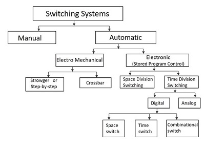
The switching systems in the early stages were operated manually. The connections were made by the operators at the telephone exchanges in order to establish a connection. To minimize the disadvantages of manual operation, automatic switching systems were introduced.
The Automatic switching systems are classified as the following −
Electromechanical Switching Systems − Here, mechanical switches are electrically operated.
Electronic Switching Systems − Here, the usage of electronic components such as diodes, transistors and ICs are used for the switching purposes.
Electromechanical Switching Systems
The Electromechanical switching systems are a combination of mechanical and electrical switching types. The electrical circuits and the mechanical relays are deployed in them. The Electromechanical switching systems are further classified into the following.
Step-by-step
The Step-by-step switching system is also called the Strowger switching system after its inventor A B Strowger. The control functions in a Strowger system are performed by circuits associated with the switching elements in the system.
Crossbar
The Crossbar switching systems have hard-wired control subsystems which use relays and latches. These subsystems have limited capability and it is virtually impossible to modify them to provide additional functionalities.
Electronic Switching Systems
The Electronic Switching systems are operated with the help of a processor or a computer which control the switching timings. The instructions are programmed and stored on a processor or computer that control the operations. This method of storing the programs on a processor or computer is called the Stored Program Control (SPC) technology. New facilities can be added to a SPC system by changing the control program.
The switching scheme used by the electronic switching systems may be either Space Division Switching or Time Division Switching. In space division switching, a dedicated path is established between the calling and the called subscribers for the entire duration of the call. In time division switching, sampled values of speech signals are transferred at fixed intervals.
The time division switching may be analog or digital. In analog switching, the sampled voltage levels are transmitted as they are. However, in binary switching, they are binary coded and transmitted. If the coded values are transferred during the same time interval from input to output, the technique is called Space Switching. If the values are stored and transferred to the output at a time interval, the technique is called Time Switching. A time division digital switch may also be designed by using a combination of space and time switching techniques.
Telecommunication Network
A Telecommunication network is a group of systems that establishes a distant call. The switching systems are part of a telecommunication network.
The switching stations provide connection between different subscribers. Such switching systems can be grouped to form a telecommunication network. The switching systems are connected using lines called the Trunks. The lines that run to the Subscriber premises are called the Subscriber Lines.
The following figure shows a telecommunication network.
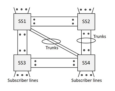
From the early to the later stages of the 20th Century (1900-80), when a person needed to make a distant call, the call was first routed to the operator at the nearest switching center and then the number and location of the called subscriber was noted down. Here, the job of the operator was to establish a call to the remote switching center and then recall the calling subscriber to establish the connection. This system of making calls was called the Trunk call system.
For example, a person at Hyderabad can book a trunk call to Mumbai and wait for the operator to call back when the operator establishes connection through the trunk lines and the switching systems.
Basics of a Switching System
In this section, we will learn about the different components and terms used in switching systems.
Inlets and Outlets
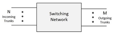
The set of input circuits of an exchange are called Inlets and the set of output circuits are called the Outlets. The primary function of a switching system is to establish an electrical path between a given inlet-outlet pair.
Usually, N indicates the inlets and the outlets are indicated by M. So, a switching network has N inlets and M outlets.
Switching Matrix
The hardware used to establish connection between inlets and outlets is called the Switching Matrix or the Switching Network. This switching network is the group of connections formed in the process of connecting inlets and outlets. Hence, it is different from the telecommunication network mentioned above.
Types of Connections
There are four types of connections that can be established in a telecommunication network. The connections are as follows −
- Local call connection between two subscribers in the system.
- Outgoing call connection between a subscriber and an outgoing trunk.
- Incoming call connection between an incoming trunk and a local subscriber.
- Transit call connection between an incoming trunk and an outgoing trunk.
Folded Network
When the number of inlets is equal to the number of outlets for a switching network, such a network is called the Symmetric Network, which means N=M. A network where the outlets are connected to the inlets, is called the Folded Network.
In a Folded Network, the N number of inlets which come as outlets are again folded back to the inlets. Nevertheless, the switching network provides connections to the inlets and outlets as per the requirement. The following figure will help you understand how the Switching Network works.
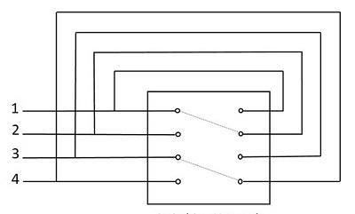
As one connection can be given to one line per time, only N/2 connections are established for N inlets of a folded network. Such a network can be called as Non-blocking network. In a non-blocking network, as long as the called subscriber is free, a calling subscriber will be able to establish a connection to the called subscriber.
In the above figure, only 4 subscribers were considered - where line 1 is busy with line 2 and line 3 is busy with line 4. While the call is in progress, there used to be no chance for making another call and hence, only a single connection was made. Hence for N inlets, only N/2 lines are connected.
At times, it might happen that the inlet and outlet connections are continuously used to make Transit calls through trunk lines only, but not among the local subscribers. The inlet and outlet connections if used in an Inter-exchange transmission such that the exchange does not support connection between local subscribers, then it is called the Transit Exchange. A switching network of such kind is called the Non-folded network. This is shown in the following figure −
Blocking Network
If there are no switching paths free in the network, the call requested will be denied, where the subscriber is said to be blocked and the network is called the Blocking Network. In a blocking network, the number of simultaneous switching paths is less than the maximum number of simultaneous conversations that can take place. The probability that a user may get blocked is called the Blocking Probability. A good design should ensure low blocking probability.
Traffic
The product of the calling rate and the average holding time is defined as the Traffic Intensity. The continuous sixty-minute period during which the traffic intensity is high is the Busy Hour. When the traffic exceeds the limit to which the switching system is designed, a subscriber experiences blocking.
Erlang
The traffic in a telecommunication network is measured by an internationally accepted unit of traffic intensity known as Erlang (E). A switching resource is said to carry one Erlang of traffic if it is continuously occupied through a given period of observation.
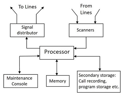
TSSN - Elements of a Switching System
In this chapter, we will discuss the elements of a switching system. Though there are different kinds of switching systems from manual to automatic, a few basic elements play an essential role for the functioning of a switching system. Along with the switching network, there are different sub systems such as control sub system, signaling system, trunk and subscriber line interfaces, distributor units, operator console, juncture circuits, essential for the operation of the whole switching system.
Switching System
In this section, we will understand the structure of the switching system. We will also understand how the different elements work in it. The block diagram of the switching system given below show the essential elements of a switching system.
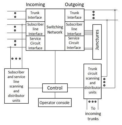
The diagram shown above contains different blocks of the switching system. The blocks are discussed below.
Switching Network
It provides the switching paths between the called subscribers and the calling subscribers.
Control Subsystem
This is the critical part of the switching system, which actively establishes the switching paths, by identifying the inlet and outlet lines and interpreting the signaling information received on these lines.
This control subsystem, controls the making and breaking of the connection by sensing the signal transfer on the lines. The control sub system sends out signaling information to the subscriber and other exchanges connected to the outgoing trunks.
Signaling
The signaling formats and requirements for the subscriber, the trunks and the sub systems differ significantly. Accordingly, a switching system provides for three different forms of signaling −
- Subscriber loop signaling
- Interexchange signaling
- Intraexchange or register signaling
A switching system is composed of elements that perform switching, control and signaling functions.
Trunk Interface
The Trunk lines used for connections between the switching systems, are terminated at this port. The Trunk interface is the point where the trunk lines are connected to the system.
Subscriber Line Interface
The Subscriber lines used for connections between the subscribers and the switching systems are terminated at this port. The subscriber line interface is the point where the lines from the subscribers are connected to the system.
Line Scanning Unit
The line scanning unit senses and obtains the signaling information from the respective lines. The information obtained from these lines are given to the control sub system to identify the inlets and outlets.
Distributor Units
The distributor units are used for distributing or sending out the signaling information on the respective lines. The distribution of information through the trunk lines, is done through the distribution units.
Operator Console
The operator console permits interaction with the switching system for maintenance and administrative purposes.
Service Circuit Interface
The service circuit interface provides interaction between circuits for maintenance and testing purposes.
Junctures
The Junctures is a junction that provides a folded connection for the local subscribers and the service circuits. If the called subscriber and the calling subscriber both are local, then the folded connection helps in making the connection to a local call, whereas the trunk lines will not be in use.
Direct and Indirect
The switching systems are of the following two types −
- the direct control switching system
- the indirect control switching system
Direct Control Switching System
The Switching systems where the control sub systems form an integral part of the network are called the Direct Control Switching systems. For example, the Strowger switching system.
Indirect Control Switching System
The Switching system in which the control sub system is present outside the switching network is called the Indirect Control Switching system or the Common Control Switching system or the Register Control switching system. The examples of this system include Crossbar switching system, Electronic switching system or Stored Program Control method of switching systems.
TSSN - Strowger Switching System
In this chapter, we will discuss how the Strowger Switching system works. The first ever automatic telephone switching was developed by Almon B Strowger. As the operator at the Manual telephone exchange was the wife of his competitor and was diverting all the business, Strowger thought of developing a switching system, which does not require an operator. This led to the invention of the automatic switching system developed by Strowger.
The Strowger Switching system is also called the step-by-step switching system as the connections are established in a step-by-step manner.
Automatic Switching System
The Manual Switching system requires an operator who after receiving a request, places a call. Here, the operator is the sole in-charge for establishing or releasing the connections. The privacy of the calls and the details of the called and the calling subscribers are at stake.
Overcoming the disadvantages of Manual Switching systems, the Automatic Switching systems come with the following advantages −
Language barriers will not affect the request for connection.
Higher degree of privacy is maintained.
Faster establishment and release of calls is done.
Number of calls made in a given period can be increased.
Calls can be made irrespective of the load on the system or the time of the day.
Let us now throw some light on how a call is made and how dialing is done without the help of an operator.
Dialing
Unlike in Manual Switching system, an automatic switching system requires a formal numbering plan or addressing scheme to identify the subscribers. Numbering plan is where a number identifies a subscriber, is more widely used than the addressing scheme in which a subscriber is identified by the alpha numerical strings. So, there needs to be a mechanism to transmit the identity of the called subscriber to the exchange.
This mechanism should be present in the telephone set, in order to connect the call automatically to the required subscriber. The methods prevalent for this purpose are Pulse Dialing and Multi Frequency Dialing. Of them, the Pulse dialing is the most commonly used form of dialing till date.
Pulse Dialing
As the name implies, the digits that are used to identify the subscribers are represented by a train of pulses. The number of pulses in a train is equal to the digit value it represents except in the case of zero, which is represented by 10 pulses. Successive digits in a number are represented by a series of pulse trains. These pulses have equal number of time intervals and the number of pulses produced will be according to the number dialed.
Two successive trains are distinguished from one another by a pause in between them, known as the Inter-digit gap. The pulses are generated by alternately breaking and making the loop circuit between the subscriber and the exchange. An example pulse train is shown in the following figure.
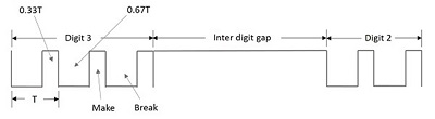
The above figure shows the pulsating pattern. The pulse rate is usually 10 pulses per second with a 10 percent of tolerance. The gap between the digits, which is called the Inter-digit gap is at least 200ms.
The pulse dialing pattern in recent times employs the duty ratio (ratio between the pulse width and the time period of the waveform) of the pulse as 33 percent nominally and there exists an upper limit for the inter-digit gap.
Rotary Dial Telephone
In this section, we will learn about what the Rotary Dial Telephone is and how it works. To start with, we will discuss the drawbacks that were prevalent before the invention of the Rotary Dial Telephone.
The pulse dialing technique is where there is making and breaking of the subscriber loops. This might disturb and affect the performance of speaker, microphone and bell contained in the telephone. In addition, the dialing timings should not affect the timing of the pulse train as this will lead to the dialing of a wrong number.
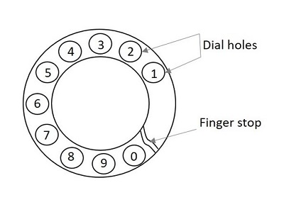
The Rotary Dial Telephone came into existence to solve the problems prevailing then. The microphone and the loudspeaker are combined and placed in the receiver set. The set has a finger plate the arrangement of which makes the dialing time appropriate. The below figure shows how a rotary dial looks like.

The dial is operated by placing the finger in the hole appropriate to the digit to be dialed. Now, drawing the fingerplate round in the clockwise direction to the finger stop position and letting the dial free by withdrawing the finger, makes a number dialed. The fingerplate and the associated mechanism now return to the rest position under the influence of a spring. The dial is ready for the next number.
The dial pulses are produced during the return travel of the fingerplate, thus eliminating the human element in pulse timings. The following figure shows the dial holes and finger stop.
A rotary dial phone uses the following for implementing pulse dialing −
- Finger plate and spring
- Shaft, gear and Pinion wheel
- Pawl and ratchet mechanism
- Impulsing cam and suppressor cam or a trigger mechanism
- Impulsing contact
- Centrifugal governor and worm gear
- Transmitter, Receiver and bell by-pass circuits
Internal Mechanism
The cam mechanism or trigger mechanism helps in dialing. This mechanism is used in operating the Impulsing contact. Let us consider the operation of the rotary dial telephone using the cam mechanism. The following figure will help you understand the internal mechanism.
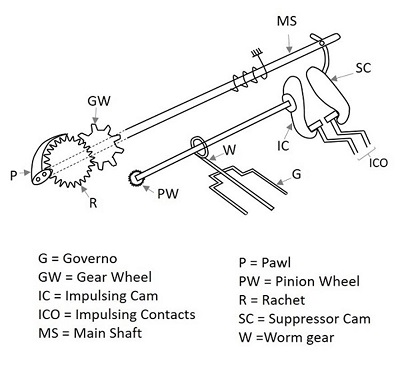
The suppressor cam helps in keeping the Impulsing cam away from the Impulsing contacts. When the rotary dial is in rest position, then the Impulsing contacts are away from the Impulsing cam. When a number is dialed, by placing the finger in the dial hole, which means the dial is displaced from its position, then the Impulsing contacts come near the Impulsing cam. This rotation of the finger plate, causes the rotation of the Main shaft.
As the dial is rotated in clockwise direction, the pawl slips over the ratchet during this clockwise rotation. The ratchet, gear wheel, pinion wheel and the governor are all stationary during the clockwise movement of the dial. When the dial returns, the pawl engages and rotates the ratchet.
All the gear wheel, pinion wheel, the governor rotate, and the uniformity in the speed of the rotation are maintained by the governor. The Impulsing cam, which is attached to a pinion shaft, now breaks and makes the Impulsing contacts that in turn causes the pulses in the circuit. The shape of the Impulsing cam is such that the break and make periods are in the ratio of 2:1. When the dial is about to reach the rest position, the suppressor cam again, moves the Impulsing contacts away from the Impulsing cam. This action of getting back to the rest position and waiting for the other number to be dialed creates a gap called the Inter-digit gap, the timing of which is independent of the pause that may occur between two successive digits, due to human dialing habit. This gap is also provided prior to the dialing of the first digit through a small change in the suppressor cam design.
The Pulse generated through this mechanism is then transmitted to the switching systems where the connection to the dialed number is established. The procedure of switching systems is discussed in a subsequent chapter. Meanwhile, let us have an idea on the signaling tones that are used to indicate the condition of the subscribers.
Signaling Tones
In this section, we will understand what are signaling tones and how these work. As the manual exchanges were replaced, the operator who used to communicate the calling subscribers regarding the situation of the called subscribers, needed to be replaced with different tones indicating different situations.
Consider the following five subscriber related signaling functions that are to be performed by the operator −
Respond to the calling subscriber that system is ready to receive the identification of the called party.
Inform the calling subscriber that the call is being established.
Ring the bell of the called party.
Inform the calling subscriber, if the called party is busy.
Inform the calling subscriber, if the called party line is unobtainable for some reason.
The function 2 is not signaled in the Strowger switching system. The signaling function 1 is fulfilled by sending a dial tone to the calling subscriber.
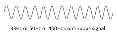
Dial Tone
The dial tone is the signaling tone, which indicates that the exchange is ready to accept the dialed digits from the subscriber. The number should be dialed only when this signal is heard. Otherwise, the digits dialed before this signal will not be considered. This will lead to the dialing of a wrong number.
The dial tone is generally a 33 Hz or 50 Hz or 400 Hz continuous tone as shown below.
Ring Tone
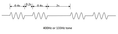
After dialing the number of the called party, when the line of the called party is obtained, the exchange control equipment sends out the ringing current to the telephone set of the called party, which is a familiar double-ring pattern.
Simultaneously, the control equipment sends out a ringing tone to the calling subscriber, which has a pattern similar to that of the ringing current. The two rings double-ring pattern are separated by a time gap of 0.2s and two double-ring patterns by a gap of 2s, as shown in the below figure.
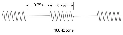
Busy Tone
After dialing the required number, if the called subscriber or the lines at the exchange are not free to place a call, the calling subscriber is sent a busy tone indicating that the lines or the subscriber is busy; this is called a busy tone.
A busty tone of 400Hz signal with silence period in between. The burst and silence durations have the same value of 0.75s or 0.75s.
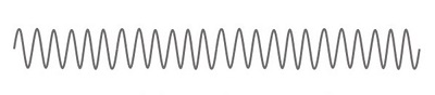
Number Unobtainable Tone
If the called party is out of order or disconnected or if an error in dialing leads to the selection of a spare line, such a situation is indicated using a continuous 400Hz signal, called as Number Unobtainable tone. The following illustration shows a continuous 400Hz signal.
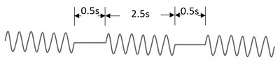
Routing Tone or Call-in-Progress Tone
When a subscriber call is routed through a number of different types of exchanges, one hears different call-in-progress tones as the call progresses through different exchanges. Such a signal is a 400Hz or 800Hz intermittent pattern. This signal has different patterns in different systems.
In electromechanical systems, it is usually 800Hz with 50 percent duty ratio and 0.5s ON/OFF period.
In analog electronic exchanges, it is a 400Hz pattern with 0.5s ON period and 2.5s OFF period.
In digital exchanges, it is 400Hz signal with 0.1s ON/OFF periods.
The signal for routing tone or call-in-progress tone is as shown below.
In order to overcome the problem of recognizing the difference in these tones for those who are not familiar with telephone signaling and for those who rarely make calls, voice recorded messages were introduced, later on.
TSSN - Switching Mechanisms
In this chapter, we will discuss the switching mechanisms in Telecommunication Switching Systems and Networks.
In our previous chapters, we discussed the mechanism in the telephone set. Let us now see what happens when this telephone set sends a signal to the switching system. The switching system at the exchange should be able to connect the line automatically to the called subscriber. In the Strowger switching system, there are two types of selectors; these selectors form the building blocks for the switching systems.
- Uni-selector
- Two-motion selector
Both of these selectors are constructed using electro-mechanical rotary switches. The Uni-selector has a single selector pole and multiple throws to reach the bank of contacts for each number dialed. The two-motion selector has two rotary switches for vertical and horizontal stepping movement, to reach the bank of contacts.
Uni-selector Switching
The Uni-selector switching mechanism consists of an Electromagnet, an Armature with springs, a Pawl, a ratchet wheel with wiper attached and a detent. The wiper is made to move on the bank contacts in clock-wise direction. As the wiper moves in one-direction, the process is called Uni-selector switching. The contacts onto which the wiper moves are called Bank contacts as a number of contacts are placed in this shape of an arc.
The following figure shows the drive mechanism of the Uni-selector Strowger switching system.
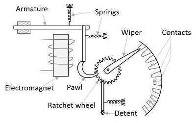
When the input voltage energizes the Electromagnet, the armature is pulled down towards the magnet. Now as the armature gets attracted towards the electromagnet, the pawl falls one position down the previous one in the ratchet wheel. The detent prevents the movement of the ratchet wheel.
Once the electromagnet gets de-energized, the armature is released and this action moves the pawl upwards, which further moves the ratchet wheel to one position above. Hence, the wiper moves one position below or in clockwise direction, to make a contact. If the electromagnet is energized and de-energized five times, by applying five pulses, the wiper moves by five contacts. Usually three sets (or more) of wipers are placed associated with the banks of Uni-selector, one for each bank. The sets are rigidly mounted to a wiper assembly, which moves whenever the ratchet wheel rotates. The interrupter spring releases the magnet and enables it to make another step.
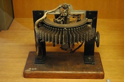
The following figure shows a practical Uni-selector Strowger switching system.
The type of switching mechanism discussed here is known as the reverse drive type because, here the ratchet wheel moves when the armature return to its rest position. If it is arranged such that the wheel moves during the forward motion of the armature it is known as the forward drive type. The Reverse drive type mechanism is prevalent in uni-selectors and the forward drive type mechanism in the two-motion selectors.
There is an interrupter contact associated with the Uni-selector, which is normally closed. When the armature is energized, the interrupter contact opens and allows the movement of armature, which helps the armature return to its rest position after breaking up the armature energizing circuit.
Two-motion Selectors
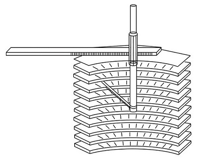
Unlike in Uni-selector, the motion in these selectors is two-way, vertical and horizontal. An upward movement is made in vertical and horizontal directions; there are no contacts made in the vertical movement. However, bank contacts are made in the horizontal movement. If the two-motion selector has 10 levels, each having 10 contacts, then 100 contacts are accessible, by the vertical and horizontal movement of the two-motion selector switching system.
The following figure shows the internal structure of two-motion switching selectors.
When the first digit is dialed, the pulses energize and de-energize the vertical magnet according to the number dialed, with the help of ratchet and pawl mechanism. This is called as Vertical Stepping.
When the second digit is dialed, the dialing pulses are diverted to horizontal magnet, with the help of a relay where the pulses energize and de-energize the horizontal magnet according to the number dialed, with the help of ratchet and pawl mechanism. This is called Horizontal Stepping.
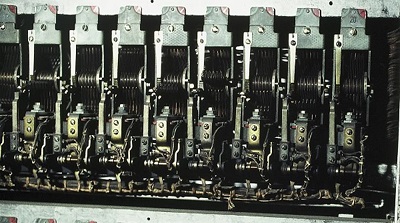
Normally, there are 11 vertical positions and 11 horizontal contacts in each vertical position. The lowest vertical position and the first horizontal contact in each vertical level are home positions, and the remaining ones are actual switching positions. Thus, the wiper in a two-motion selector has access to 100 switching contacts. The following figure shows a practical two-motion switching selector.
Thus, the wiper assembly establishes the call; after completion of which it comes back to the home position. For this purpose, the rotary magnet is operated by the current and thus the wiper assembly moves through the remaining contacts of the level. A restoring spring forces the wiper assembly to drop vertically and then return horizontally to the home position.
Step-by-Step Switching
The Step-by-step switching system is a very popular and widely-used switching system, which may be constructed using Uni-selectors or two-motion selectors or the combination of both. The wiper present in this switching, steps forward by one contact and then moves forward according to the number of dialed pulses or according to the signaling conditions and hence the name, step-by-step switching is given.
A step-by-step switching is also called the Direct control system as the relevant signaling tones are sent out to the subscriber by the switching elements or selectors at the appropriate stages of switching. This system has three main stages of configuration. The following figure shows the different stages.
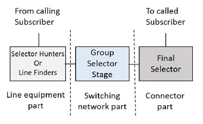
Let us now see how these blocks function.
Selector Hunters
As soon as the calling subscriber gets ready to dial the number, by lifting the handset from the telephone, a dial tone is heard. We have already learnt that a number is not accepted unless the dial tone is heard. But to get that dial tone, the line has to be established when the handset is lifted up. The Selector Hunter circuit, establishes the line to make a call as immediately as the calling subscriber lifts up the handset to make a call.
The Selector Hunters hunt for selecting a switching matrix part. Usually, 24-outlet Uni-selectors are used as selector hunters. and so this can be called as Subscriber Uni-selector scheme as there is a dedicated Uni-selector for each subscriber in the system. These can also be build using two-motion selectors.
The selector hunter mechanism can also be replaced with the line finder mechanism, where there is small difference between the two in construction. Here, we shall discuss the selector hunter mechanism. The figure below gives an idea about its construction.
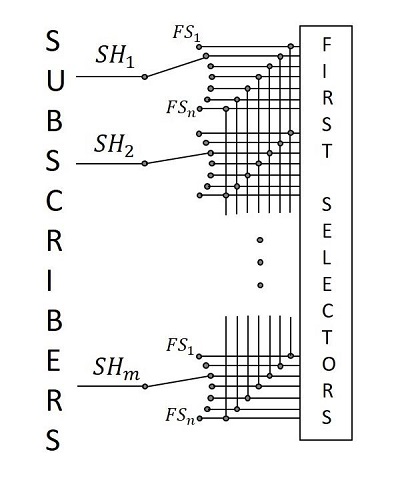
When a calling subscriber lifts the handset to make a call, the selector hunter activates the interrupter mechanism, which steps up the wiper until a free first group selector is found at the outlet. One of the bank contacts of the selector hunter, at this point, senses whether the first group selector is free or busy. Once a free first selector is sensed, the interrupter is disabled and the connection is established, where the first selector sends out a dialer tone to the calling subscriber.
The line finder approach is used where the traffic is low and the exchange is small, whereas the selector hunter mechanism described above is used for large exchanges with heavy traffic and this approach is cost-effective.
Group Selector Stage
The Group Selector stage has the main switching network. The calling subscriber dials the number after hearing the dial tone. The first number when dialed activates the first selector. To be more precise, the group selector consists of certain selector stages. We used to have 5 numbers as an identification number, for the land connection. Hence, there were three selector stages present.
To dial the first number, the number plate is rotated by placing the finger in the finger gap given according to the subscriber number. After taking out the finger, the number plate is rotated back to its previous position, which sends the dialing pulses to the first selector. The first selector then moves accordingly, to place a contact.

When the subscriber starts dialing, the dial tone produced till then, cuts off and the pulse train is received according to the number dialed. The wiper assembly of the first selector then moves vertically upward, according to the number dialed. The wipers then move in the horizontal plane across the contacts until they come across a contact to which a free second group selector is connected. This horizontal stepping is completed within the inter-digit gap of about 240ms. From there, the first group selector connects the electrical path to the available second group selector.
Likewise, every group selector connects path according to the number dialed and then extends the connection to the next selector until the final selector. The action of the final selector is a bit different. As discussed above, three selectors are present and the fourth and the fifth numbers are connected to the matrix by the final selector.
Final Selector
The last two digits are processed by the final selector. This selector moves vertically according to the fourth digit dialed and then it moves horizontally according to the last digit, as there are no further digits to connect it to some other connector. The last digit dialed, establishes electrical connection to the called subscriber.
Since the final selector responds to both the digits in vertical and horizontal directions unlike the group selectors, this final selector is also called a Numerical Selector. If the called subscriber is free, as sensed from a signal at the corresponding bank contact, the final selector sends out a ringing current to the called subscriber and a ringing tone to the calling subscriber.

When the called subscriber lifts his handset, the ringing current and the ringing tone provided till then, are cut off and the call metering circuits are enabled by the control circuits associated with the final selectors. Otherwise, if the called subscriber is found to be busy on some other line, then the final selector sends out a busy tone to the calling subscriber. At any stage of switching, if there is no free selector available at the next stage, a busy tone is returned to the calling subscriber.
The magnets and mechanical linkages used in rotating the shafts vertically and horizontally while connecting a call, will release the magnet (generally called the release magnet) and armature release the shaft when the call is completed.
TSSN - Common Control Subsystem
In this chapter, we will discuss how the Common Control Subsystem works in Telecommunication Switching Systems and Networks.
In order to establish calls between different exchanges, which may further lead to a long distance trunk call, the Crossbar switching system was developed and the first patent was given in 1915. However, AT&T developed the first Crossbar switching system in 1938. The Crossbar switching system introduced the Common Control Subsystem in its switching system.
To understand this, let us have an idea on the problem created by Multi-exchange network of the Strowger system.
Multi-Exchange Network
When a subscriber belonging to a particular network has to be contacted, a number of ways can help you contact the particular exchange; also, there is not one but any exchanges present in the route.
In a Multi exchange network, the routes used to establish connection with a particular subscriber differs from time to time. In the Strowger exchange following the Multi-exchange network, the subscriber has to be more concerned with the routing. A subscriber should have the details of all the numbers of exchanges present in the route. There may arise situations where a subscriber may be required to establish a connection on other routes; this becomes cumbersome at times.
The following figure is an example of the topology of a Multi-exchange network.
The level is reserved in each Strowger exchange, where the outgoing calls are connected to neighboring exchanges. These exchanges are contacted as per the exchange numbers dialed, when the calls are made.
Hence, the disadvantages of implementing Multi-Exchange network in switching are −
The subscriber identity number is changed depending on the calling route.
The user must have knowledge on the topology of the network and the numbers of the exchanges present in it.
The number and size of the called subscriber varies depending upon the exchange from where the call originates.
In order to overcome these problems, the common control subsystem was introduced.
Common Control Subsystem
In order to avoid the complication and to make it easier for a subscriber to place a call, two main ideas were implemented by the Common Control Sub system. The ideas are listed below −
The routing of the call should be done by the exchange, but not by the numbers dialed.
A Unique Identification Number should be allotted to the subscriber. The UIN contains the number of the exchange of the subscriber and the number indicating the line of the subscriber.
A Unique Identification Number should be allotted to the subscriber. The UIN contains the number of the exchange of the subscriber and the number indicating the line of the subscriber.
Exchange Identifier + Subscriber Line Identifier
This is a combination of STD (Subscriber Trunk Dialing) code and the subscribers number; consider this as the physical line address. Every user is assigned a logical number irrespective of the physical line number. An Address translation mechanism translates the logical address to actual physical address for connection establishment. The call processing takes place independent of the switching network.
A Director system is employed in the common control sub system. As soon as the translated digits are transmitted, the Director is free to process another call and is not involved in maintaining the circuit for the conversation.
The following figure shows the diagram of the Common Control Subsystem, which contains Call Processing Sub system, Charging Circuits, Operation Control, Maintenance Control and Event Monitor.
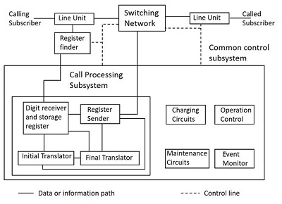
The above block diagram is a simple indication of the common control switching system. The control functions in a switching system can be categorized as the following.
Event Monitoring
Event Monitoring Section of the Control Subsystem monitors the events occurring outside the exchange at the line units, trunk junctures and inter exchange signaling and sender/receiver units. The events at the line units are - call request and call release. The control of relays to establish connection to the required line is an event at the junctures. There is control of relays between the exchanges for connection and also for signaling the required tones both to the sender and receiver circuits at the inter exchange. This event monitoring may be distributed.
Call Processing
The Call Processing units contain digit receiver and storage register, which receive and store the dialing number from the calling party. The units also contain the initial and final translators. The Initial translator is the Office Code translator that determines the route for the call through the network or charging method or rate. The Final translator is the Subscriber Code translator which determines the line unit to which a call must be connected and category of the called line. The Register Sender transfers the route digit and dialed digit using proper signaling, depending on the requirements of the destination exchange.
Charging
This is related to the charges levied on the calls made. It depends upon the type of subscriber and the service of the subscriber. For example, some services like emergency lines or fault repairs are free of charge; a few commercial services also may offer charge-free services.
Operation and Maintenance
The control and operation of the switching network with two main techniques known as Map-in-memory and Map-in-network.
Map-in-Memory
The path in this technique is determined by marking the switching elements at different stages in accordance with a set of binary data defining the path, whereas the control unit supplies the data. At this stage, the command for the actual connection of the path is given. This Map-in-memory technique is present in Stored Program Control.
Map-in-Network
In this technique, the Path finding may be carried out at the level of common control unit, where it marks the inlet and outlet to be connected and the actual path is determined by the switching network. This Map-in-Network technique is common in Crossbar exchanges using markers for control.
The administration and maintenance of a switching system, involves activities such as laying the new subscriber lines and trunks into service, modifying subscriber service entitlements and changing routing plans based on the network status, which are performed with the coordination of control systems. Maintenance personnel do the maintenance activities such as supervision for proper functioning, performing tests and making measurements for different line parameters.
TSSN - Touch-tone Dial Telephone
In this chapter, we will learn about the Touch-tone Dial Telephone technology. When we talk about the technological development of the telephone set, the rotary dial was used in the initial stages. Slower dialing was one major disadvantage associated with the Rotary dial. It took 12 seconds to dial a 7-digit number on a Rotary dial. The step-by-step switching elements of the Strowger switching system, cannot respond to rates higher than 10-12 pulses per second.
It uses the DTMF technology, prior to which the pulse dialing technique was used. In the Pulse dialing technique which is also called a Loop disconnect technique, repeated connecting and disconnecting of the lines is done, like clicks of a switch; this is interpreted by the exchange as the number dialed, according to the number of clicks.
Need for Touch-tone
With the introduction of the Common Control subsystems into switching exchanges, there came the feasibility for higher rates of dialing. Hence, a new system called the Touch-tone dialing was developed in Telephony to replace the Rotary dial; this was considered to benefit the customer with higher speed. This has also removed the disadvantages of limited usage and limited signaling capacity along with lower speed.
The Pulse dialing is limited to signaling between the exchange and the subscriber, but not between two subscribers, which is called End-to-End signalling. End-to-End signaling is a desirable feature and is possible only if the signaling is in voice frequency band so that the signaling information can be transmitted to any point in the telephone network to which voice can be transmitted.
Hence replacing the inconvenience of using the rotary dial, the touch-tone dial telephone was introduced. The development of the touch-tone dial telephone came around 1950. However, the usage of it started somewhere around 1964. The following figure shows a practical touch-tone dial telephone.
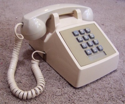
The above figure will help you understand that the rotary dial is replaced with a push button keyboard, where the buttons, if touched to press the button will generate frequencies related to the number dialed. The hassle-free rotation was replaced and a feature to redial the number was added to this push button keyboard, where the dialed number is stored until another number is dialed. This eased the process of redialing a 7- digit number all over again.
How does the Touch-tone Dial Telephone Operate?
The press of a button on the touch-tone dial telephone indicates the number dialed using certain frequencies. Touching or light pressing of a number generates a tone which is a combination of two frequencies, one from lower band and the other from upper band.
For example, by pressing the button 9, two frequencies such as 852 Hz the lower frequency and 1477Hz the upper frequency are produced. The design of touch-tone dialing producing two frequencies is as shown below.
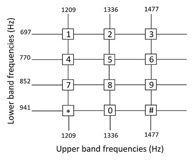
The DTMF (Dual-tone Multi-frequency) dialing can be done through the touch-tone dialing technique as shown above. As two frequencies, one being higher and the other being lower are transmitted at the same time in the touch-tone dialing technique, it is called the Dual-tone Multi Frequency (DTMF) dialing. The two signals produced are for a duration of 100ms, which are selected by the key pressed from the matrix as shown above. Each key is uniquely referenced by selecting one of the four lower band frequencies associated with the matrix rows, coupled with selecting one of the three higher band frequencies associated with the matrix column.
Design Considerations
The design considerations are
- Choice of Code
- Band Separation
- Choice of Frequencies
- Choice of Power Levels
- Signaling Duration
The choice of code for touch-tone signaling should be such that the imitation of code signals by music and speech must be difficult.
Consider the following reasons for separating the band of two frequencies −
At the receiver, band filtering is used to separate the frequency groups; this helps to determine the specific frequencies in a simple way.
Easy amplitude regulation of each frequency component separately.
Limiters can be used to guard the action of each frequency separately.
The probability of false response is reduced.
The attenuation and delay distortion characteristics of the telephone network circuits determine the choice of frequencies. A flat amplitude response with a very low attenuation and a uniform delay response with a low relative delay value are desirable. Though the design is high enough for reliability, the choice of power levels should be planned according to attenuation characteristics of the channel. The signal duration although inefficient is longer and helpful to combat talk-off.
Internal Mechanism
The internal mechanism of the touch-tone receiver can be explained by a simple block diagram which contains Band Separation Filter (BSF), Limiters (L), Selector Circuits (S) and Detectors (D) which give out Low Band Frequency (LBF) signals and High Band Frequency (HBF) signals, as indicated below.
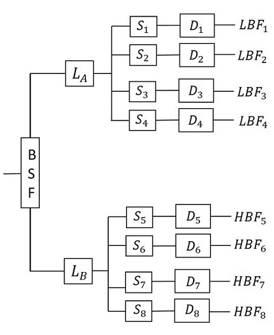
The Band separation filter present at the receiver is used to separate the frequency groups. This helps to determine the specific frequencies, separately. In addition, the filter also regulates the amplitudes of each component. Then the signal reaches the limiter, which has two of the frequencies at its input. It allows the dominant signal through it bypassing the weak signal. If both of the signals have the same strength, the limiter output is much below the full output and neither of the signal dominates.
The selectors present in the circuitry, are designed to recognize the signal when it falls within the specified narrow passband and has an amplitude within the range of 2.5dB of full output of the limiter. Both of the limiter and selector circuits are efficient in recognizing the difference between the touch-tone and the voice signal, to avoid talk-off. For further improvement, Band Elimination filters are sometimes used in place of Band Separation filters as they permit a wide spectrum of speech to pass through the filters. The high and low band frequency signals reach the output separately through the detector outputs.
TSSN - Crossbar Switching
In this chapter, we will discuss the concept of Crossbar Switching. The Crossbar exchanges were developed during 1940s. They achieve full access and non-blocking capabilities with the Crossbar switches and common control equipment, used in the Crossbar exchanges. The active elements called Crosspoints are placed between the input and the output lines. In the common control switching systems, the separation between switching and control operations allows the usage of switching networks by a group of common control switches to establish many calls at the same time on a shared basis.
The Features of Crossbar Switches
In this section, we will discuss the different features of the Crossbar Switches. The features are described in brief below −
While processing a call, the common control system helps in the sharing of resources.
The specific route functions of call processing are hardwired because of the Wire logic computers.
The flexible system design helps in the appropriate ratio selection is allowed for a specific switch.
Fewer moving parts ease the maintenance of Crossbar switching systems.
The Crossbar switching system uses the common control networks which enable the switching network to perform event monitoring, call processing, charging, operation and maintenance as discussed previously. The common control also provides uniform numbering of subscribers in a multi-exchange area like big cities and routing of calls from one exchange to another using the same intermediate exchanges. This method helps to avoid the disadvantages associated with the step-by-step switching method through its unique process of receiving and storing the complete number to establish a call connection.
Crossbar Switching Matrix
The Crossbar arrangement is a matrix which is formed by the M X N sets of contacts arranged as vertical and horizontal bars with contact points where they meet. They need nearly M + N number of activators to select one of the contacts. The Crossbar matrix arrangement is shown in the following figure.
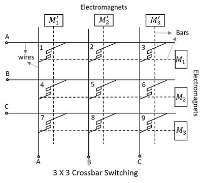
The Crossbar matrix contains an array of horizontal and vertical wires shown by solid lines in the following figure, which are both connected to initially separated contact points of switches. The horizontal and vertical bars shown in dotted lines in the above figure are mechanically connected to these contact points and attached to the electromagnets.
The Crosspoints placed between the input and the output lines have electromagnets which when energized, close the contact of intersection of the two bars. This makes the two bars to come closer and hold on. The following figure will help you understand the contact made at the Crosspoints.
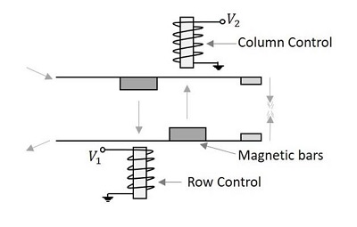
Once energized, the electromagnets pull the small magnetic slabs present on the bars. The column control electromagnet pulls the magnet on the lower bar, while the row controlelectromagnet pulls the magnet on the upper bar. In order to avoid the catching of different Crosspoints in the same circuit, a procedure is followed, to establish a connection. According to this procedure, either horizontal or vertical bar can be energized first to make a contact. However, to break a contact, the horizontal bar is de-energized first; the vertical bar being de-energized follows this.
As all the stations are allowed to be connected with all possible connections as long as the called party is free, this Crossbar Switching is called the Non-Blocking Crossbar configuration, which requires N2 switching elements for N subscribers. So, the Crosspoints will be highly greater than the subscribers. For example, 100 subscribers will require a 10,000 Crosspoints. This means that this technique can be applied to a group having a small number of subscribers.
There is an external switch called the Marker; this can control many switches and serve many registers. The switch decides the operation of magnets such as the select magnet and the bridge magnet that should be energized and de-energized for connecting and releasing the subscriber respectively.
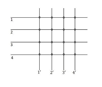
Diagonal Crosspoint Matrix
In the matrix, as 1,2,3,4 indicate input lines and 1,2,3,4 indicate output lines of the same subscribers, if a connection has to be established between the 1st and the 2nd subscriber, then 1 and 2 can be connected or 2 and 1 can be connected using the Crosspoints. In the same way, when a connection has to be established between 3 and 4, then 3-4 Crosspoint or 4-3 Crosspoint can do the work. The following figure will help you understand how this works.
Now, the diagonal portions are the Crosspoints connecting to the same subscriber again. A line that is already connected to the terminal has no need of connecting it again to the same terminal. Hence, the diagonal points are also not necessary.
So, it is understood that for N number of subscribers, if the diagonal points are also considered, the total number of Crosspoints will be,
$$\frac{N\left ( N+1 \right )}{2}$$
For N number of subscribers, if the diagonal points are not considered, then the total number of Crosspoints will be,
$$\frac{N\left ( N-1 \right )}{2}$$
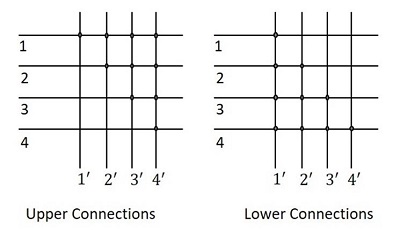
As the number of nodes N increases, the Crosspoints proportionally increase up to N2. The Crosspoints will always be linear. Therefore, as either the lower part or the upper part of the diagonal points in the matrix, can be considered, the whole matrix considering the lower portion, will now be as shown in the following figure.
This is called the Diagonal Crosspoint Matrix. The matrix is in a triangular format and can be called the Triangular Matrix or the Two-way Matrix. The diagonal Crosspoint
matrix is fully connected. When the third subscriber initiates a call, to the fourth subscriber, then the third subscribers horizontal bar is initiated first and then the fourth subscribers vertical bar is energized. The diagonal Crosspoint matrix is a non-blocking configuration. The main disadvantage of this system is that, the failure of a single switch will make some subscribers inaccessible.
The Crosspoint switch is the abstract of any switch such as the time or space switch. If N connections can be made simultaneously in an NXN switch matrix, it is called the Non-blocking Switch. If the number of connections made are less than N in some or all cases, then it is called the Blocking switch. These blocking switches are worked upon using Multiple Switches and such networks are called Line frames.
TSSN - Crossbar Switch Configurations
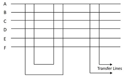
In this chapter, we will discuss how the Crossbar switch configuration works. The Crossbar switch configurations are Non-blocking configurations, which have N2 switching elements for N subscribers and can make N/2 simultaneous conversations. The usage of Crosspoint depends upon the calling subscriber.
This is a modified Non-blocking scheme with Diagonal Crosspoint matrix as discussed above having N(N-1)/2 elements. The number of elements is same as that of a fully connected network. The connection in this method is established by first energizing the horizontal bar and then the vertical bar. However, this Non-blocking scheme has few disadvantages such as −
- Large number of switching elements are required.
- This is difficult to implement in practice.
- This is neither a cost-effective process.
In order to overcome these disadvantages, the blocking Crossbar switching was introduced.
Blocking Crossbar Switches
The main aim of blocking Crossbar switches is to reduce the number of Crosspoint switches. There are single stage and multi-stage switches. The number of Crosspoint switches can be reduced with the help of two different methodologies. In the first method, two subscribers share one vertical bar. With this, the number of bars will be reduced but the number of Crosspoint switches remain the same. The second method is where all the subscribers share a number of vertical bars. With this, the number of bars and Crosspoint switches are reduced.
Method 1
This method contains 2NK switches, where N is the number of subscribers and K is the number of simultaneous connections. Four bars operate to establish a connection. If a connection has to be established between A and B, then the horizontal bar A is energized first and then one of the free vertical bars say P is energized. Now, the Crosspoint AP is latched. If the horizontal bar B is energized now, BP will not be latched, as the P vertical is energized before B was energized. To connect A and B, we need another vertical Crossbar which should electrically correspond to the vertical bar P, which is P as shown in the following figure. When this P is energized after B, the Crosspoint BP is latched and a connection between A and B is established.
The connections are as shown in the following figure.
Hence, the steps associated with the establishment of connection follows a sequence −
- Energize horizontal bar A
- Energize free vertical bar P
- De-energize horizontal bar A
- Energize horizontal bar B
- Energize free vertical bar P (associated with P)
De-energize horizontal bar B
Method 2
This method contains NK switches, where N is the number of subscribers and K is the number of simultaneous connections. Here, three bars operate to establish a connection. If a connection has to be established between A and B, then the horizontal bars A and B are energized first and then one of the free vertical bars say P is energized. Now, the connection is established using one vertical bar P only instead of two bars. The horizontal bars A and B are de-energized now.
The connections are as shown in the following figure.
Hence, the establishment of connection follows a sequence −
- Energize horizontal bars A and B
- Energize free vertical bar P
- De-energize horizontal bars A and B
Transfer Line Support
In this section, we will discuss how the Transfer Line Support works. Both of the above discussed blocking and non-blocking type Crossbar switches can support transfer lines. This is done by introducing additional vertical Crossbars and Crosspoint switches.
There are two methods to introduce additional vertical Crossbars and Crosspoint switches
- Internal non-blocking and external blocking
- Blocking both local and external
The internal non-blocking and external blocking method is as shown in the figure below.
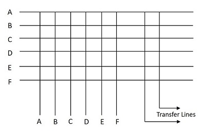
The switch shown in internal non-blocking has two transfer lines. The number of Crosspoint switches in this case is N(N+L), where N is the number of subscribers, L is the number of transfer lines.
The method of blocking both local and external is as shown in the figure below.
The switch shown in the above figure is blocking both internally and externally with two simultaneous internal and two simultaneous external calls. The number of Crosspoint switches in this case is N(2K+L), where N is the number of subscribers, L is the number of transfer lines and K is the number of simultaneous calls that can be supported locally.
TSSN - Crosspoint Technology
In this chapter, we will discuss the Crosspoint Technology in Telecommunication Switching Systems and Networks.
The Crossbar system mainly consists of the Crosspoint switches, which increases the cost of the system. The cost of the Crossbar system increases in direct proportion to the number of Crosspoint.
Challenges for the Crosspoint Technology
In this section, we will discuss the challenges associated with the Crosspoint technology. The challenges are described below −
- Reduction in the size of a Crosspoint
- Reduction in the cost of a Crosspoint
- Improvisation of the switching time
In the process of finding solutions to the existing challenges, the Crosspoint technology evolved. Crosspoint technology is an amalgamation of two related technologies. The technologies are −
- Electromechanical
- Electronic
The flowchart given below chows the different categories of the Crosspoint technology −
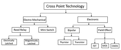
In our subsequent sections, we will discuss more about the related technologies
Electromechanical Crosspoint Technology
The Electromechanical Crosspoint switches which are capable of making and breaking contacts in 1-10ms of time duration for several million times without any wear and tear are being extensively used even today. The two types of switches widely used are Mini switches and Reed relay.
Mini Switches
These switches are made up of a precious metal like Palladium, which makes the contacts work quieter, with their bifurcated design and high resistance to corrosion for long lasting design. These mechanically latched switches use V notches for this purpose and are highly reliable in Crossbar switching systems.
These switches mounted on Crossbars move horizontally and vertically to establish and release contacts with a switching time of 8-10ms.
Reed Relay Switches
In order to reduce the usage of mechanical switches and increase the operating life of the switches further, the Reed relay switches were introduced. These switches are made up of magnetic material contacts sealed in a glass tube; this protects the contacts from getting contaminated. The following figure illustrates the design of a reed relay switch.
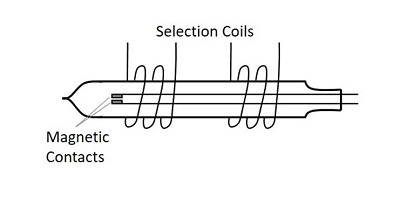
A reed relay switch may be electrically or mechanically latched; it contains the contacts very close to each other having a displacement of 0.2mm resulting in a fast switching speed of 1ms. The construction of this relay is such that the glass tube is surrounded by a pair of coils and when current is passed through both the coils simultaneously, a field is created. This further leads to the reed contacts moving together. As long as it is switched on, the electrical connection is latched and current passes through the coil.
In magnetic latching, the hysteresis of the magnetic material decides the performance. The magnetic pole pieces required may be placed outside the glass or the contacts may act as poles by choosing an appropriate ferromagnetic material. The reed relay is called the remreed due to the remnance property of the contact strips. The residual magnetism lets the contacts stay intact even after the currents are withdrawn and hence a demagnetizing current needs to be applied to open the contacts.
These reed relays are placed at each Crosspoint to construct a Crosspoint matrix. Crosspoint selection is achieved by connecting one of the coil windings of each relay in series with its vertical neighbor and the other winding in series with its horizontal neighbor. The reed relay is excited when the required Crosspoint is selected by pulsating the corresponding vertical and horizontal bars simultaneously.
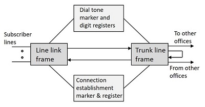
Crossbar Exchange Organization
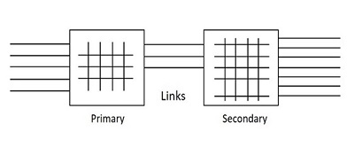
The organization of a Crossbar exchange consists of three basic building blocks such as link frames, control markers and registers. Link frames contain primary and secondary stages having Crossbars, connected with links between them. This two-stage arrangement with links has the effect of increasing the number of outlets for a given number of inlets. If the number of outlets is high, the selectivity is higher too.
The organization of a Crossbar exchange consists of three basic building blocks such as link frames, control markers and registers. Link frames contain primary and secondary stages having Crossbars, connected with links between them. This two-stage arrangement with links has the effect of increasing the number of outlets for a given number of inlets. If the number of outlets is high, the selectivity is higher too.
The two main sections of the Crossbar Exchange organization are
Line Unit
The line link frames along with associated markers and registers can be termed as Line Unit. The line units are two-way units that help in the origination and termination of calls. Because of its two-way capability, the secondary section in the line link frame is called the terminal section. The subscriber lines are terminated on the outlets of the terminal section frames.
Group Unit
The trunk link frame along with its associated circuitry can be termed as the Group Unit. The trunk link frame may be sub-divided into two or three link frames like local office link frame and incoming link frame, etc. Group unit is a uni-directional device that receives the calls from the line unit or from distant exchanges. It is capable of handling local, outgoing, incoming, terminating and transit calls.
Call Processing
A Simplified organization of a Crossbar exchange is shown in the following figure.
The call processing in a Crossbar exchange is done in three stages, named as Pre-Selection, Group Selection and Line Selection.
Pre-Selection
The originating marker does the pre-selection. When the calling subscriber lifts the handset, the dial tone is heard. The register send this tone. This stage that stars from lifting the handset to sending the dialed tone is called Pre-Selection.
Group Selection
Once the dial tone is heard, the number can be dialed. The call is switched through the desired direction as decided, in accordance with the code given by the translator. This stage of selecting the desired group for making a call is called Group Selection.
Line Selection
Once a number is dialed, the calling subscriber is connected to the called subscriber by the terminating marker. The line of the called party is controlled by the terminating marker which also sets up ringing on the line. This stage of selecting the line of the desired subscriber can be called as the Line Selection.
With these three sections, a call can be connected and processed in a Crossbar exchange
TSSN - Stored Program Control
In this chapter, we will discuss the Stored Program Control works in Telecommunication Switching Systems and Networks. In order to increase the efficiency and speed of control and signaling in switching, the use of electronics was introduced. The Stored Program Control, in short SPC is the concept of electronics that ringed in a change in telecommunication. It permits the features like abbreviated dialing, call forwarding, call waiting, etc. The Stored Program Control concept is where a program or a set of instructions to the computer is stored in its memory and the instructions are executed automatically one by one by the processor.
As the exchange control functions are carried out through programs stored in the memory of a computer, it is called the Stored Program Control (SPC). The following figure shows the basic control structure of an SPC telephony exchange.
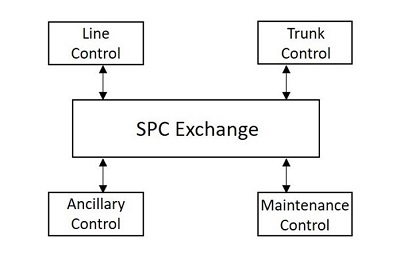
The processors used by SPC are designed based on the requirements of the exchange. The processors are duplicated; and, using more than one processor makes the process reliable. A separate processor is used for the maintenance of the switching system.
There are two types of SPCs −
- Centralized SPC
- Distributed SPC
Centralized SPC
The previous version of Centralized SPC used a single main processor to perform the exchange functions. The dual processor replaced the single main processor at a later stage of advancement. This made the process more reliable. The following figure shows the organization of a typical Centralized SPC.
A dual processor architecture may be configured to operate in three modes like −
- Standby Mode
- Synchronous Duplex Mode
- Load Sharing Mode
Standby Mode
As the name implies, in the two processors present, one processor is active and the other is in the standby mode. The processor in the standby mode is used as a backup, in case the active one fails. This mode of exchange uses a secondary storage common to both the processors. The active processor copies the status of the system periodically and stores in the axis secondary storage, but the processors are not directly connected. The programs and instructions related to the control functions, routine programs and other required information are stored in the Secondary storage.
Synchronous Duplex Mode
In the Synchronous Duplex mode, two processors are connected and operated in synchronism. Two processors P1 and P2 are connected and separate memories like M1 and M2 are used. These processors are coupled to exchange the stored data. A Comparator is used in between these two processors. The Comparator helps in comparing the results.
During the normal operation, both of the processors function individually receiving all the information from the exchange and also related data from their memories. However, only one processor controls the exchange; the other one remains in synchronism with the previous one. The comparator, which compares the results of both the processors, identifies if any fault occurs and then the faulty processor among them is identified by operating them individually. The faulty processor is brought into service only after the rectification of fault and the other processor serves meanwhile.
Load Sharing Mode
Load sharing mode is where a task is shared between two processors. The Exclusion Device (ED) is used instead of the comparator in this mode. The processors call for ED to share the resources, so that both the processors do not seek the same resource at the same time.
In this mode, both the processors are simultaneously active. These processors share the resources of the exchange and load. In case one of the processor fails, the other one takes over the entire load of the exchange with the help of ED. Under normal operation, each processor handles one-half of the calls on a statistical basis. The exchange operator can however vary the processor load for maintenance purpose.
Distributed SPC
Unlike Electromechanical switches and Centralized SPC, the introduction of Distributed SPC has enabled to provide a wide range of services. This SPC has separate small processors called the Regional Processors that deal with different works, rather than just one or two processors working on the whole thing like in the centralized system. However, when these regional processors are required to perform complex tasks, the centralized SPC helps by directing them.
The Distributed SPC has more availability and reliability than Centralized SPC, because entire exchange control functions may be decomposed either horizontally or vertically for distributed processing. Such distributed control where switching equipment is divided into parts, each of which have its own processor, is indicated in the figure below.
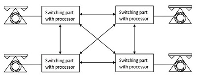
The exchange environment in vertical decomposition is divided into several blocks and each block is assigned to a processor that performs all the control functions that are related to specific block of equipment, whereas each processor in horizontal decomposition performs one or some of the exchange control functions.
TSSN - Software Architecture
In this chapter, we will learn about the Software Architecture of Telecommunication Switching Systems and Networks.
The software of the SPC systems can be categorized into two for better understanding System Software and Application Software. The Software architecture deals with the system software environment of SPC including the language processors. Many features along with call processing are part of the operating system under which operations and Management functions are carried out.
Call Processing is the main processing function, which is event oriented. The event that occurs at the subscribers line or trunk triggers the call processing. Call setup is not done in one continuous processing sequence in the exchange. This entire process is consistent of many elementary processes that last for few tens or hundreds of milliseconds and many calls are processed as such simultaneously and each call is handled by a separate Process. A Process is an active entity which is a program in execution, sometimes even termed as a task.
Process in a Multiprogramming Environment
In this section, we will see what a process in a multiprogramming environment is. A Process in a multiprogramming environment may be one of the following −
- Running
- Ready
- Blocked
The state of a process is defined by its current activity and the process it executes and the transitions that its state undergoes.
A Process is said to be running, if an instruction is currently being executed by the processor.
A Process is said to be ready if the next instruction of running a process is waiting or has an instruction that is timed out.
A Process is said to be blocked, if it is waiting for some event to occur before it can proceed.
The following figure indicates the process that shows the transition between running, ready and blocked.
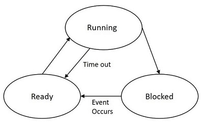
While some processes are in the running state, some will be in the ready state while others are blocked up. The processes in the ready list will be according to the priorities. The blocked processes are unordered and they unblock in the order in which the events are waiting to occur. If a process is not executed and waits for some other instruction or resource, the processor time is saved by pushing such process to the ready list and will be unblocked when its priority is high.
Process Control Block
The Process Control Block represents each process in the operating system. PCB is a data structure containing the following information about the process.
Current running state of the process
Process priority which are in the ready state
CPU scheduling parameters
Saves the content of CPU, when a process gets interrupted
Memory allocation to the process
The details of process like its number, CPU usage etc. are present
Status of events and I/O resources that are associated with the process
PCB has all the information about the processes to be executed next when it gets the CPU. The CPU registers include a Program Status Word (PSW) that contains the address of the next instruction to be executed, the types of interrupts enabled or disabled currently, etc.
While the CPU executes some process, that process needs to be switched when the currently running process becomes blocked or an event or interrupt that triggers a high priority process occurs. Such situation is called Process Switching, which is also known as Context Switching. Such interrupt priority mechanism is described in the following figure.
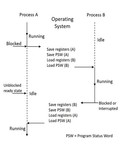
If a process A scans a particular subscriber line and finds it free, then the process establishes a call with that subscriber. However, if another process B claims the priority and establishes a call with the same subscriber at the same time, then both the processes need to make a call to the same subscriber at the same time, which is not suggestable. A similar problem might occur with other shared tables and files also.
Information about the resources of the exchange (trunks, registers etc.) and their current utilization is kept in the form of tables. These tables when needed are shared by different processes. The problem occurs when two or more processes opt for the same table at the same time. This problem can be solved by giving access to each process to a shared table.
Sharing Resources
Whenever a process uses a shared table or any shared resource, all the other processes that needs the same are to be kept waiting. When the running process finishes using the resource, it will be allotted to the first prioritized ready process which is kept waiting. This process of using the shared resources is called Mutual Exclusion. The process, which is accessing the shared resource, is said to be in its Critical Section or Critical Region. Mutual Exclusion implies that only one process can be in the critical region at any instance for a given shared resource. The coding for the process to be in the critical section is done very carefully that there are no infinite loops. This helps in the process not being blocked. The work done is more accurate and efficient. This helps the other processes that are waiting.
If two processes in a semaphore have to share a common resource, it is shared by them for certain time intervals. While one uses the resource, the other waits. Now, while waiting, in order to be in synchronism with the other one, it reads the task that was written until then. This means, the state of that process should be non-zero and should keep on incrementing, which otherwise would be sent out to the blocked list. The processes that are in the blocked list are stacked one over the other and are allowed to use the resource according to the priority.
The following figure shows how the process works −

If two or more processes in a semaphore wait indefinitely for a resource and does not get zero to return to the block state, while other processes wait in the blocked state for the use of the same resource while none could use the resource but wait, such a state is called the Deadlock State.
The techniques have been developed for deadlock prevention, avoidance, detection and recovery. Therefore, these cover the salient features of operating system for switching processors.
Software Production
The SPC software production is important because of its complexity and size of the software along with its long working life and reliability, availability and portability.
Software production is that branch of software engineering that deals with the problems encountered in the production and maintenance of large scale software for complex systems. The practice of software engineering is categorized into four stages. These stages make up for the production of software systems.
- Functional specifications
- Formal description and detailed specifications
- Coding and verification
- Testing and debugging
The Application software of a switching system may be divided into call processing software, administrative software and maintenance software; the application software packages of a switching system use a modular organization.
With the introduction of the Stored Program Control, a host of new or improved services can be made available to the subscribers. Many kinds of enhanced services such as abbreviated dialing, recorded number calls or no dialing calls, call back when free, call forwarding, operator answer, calling number record, call waiting, consultation hold, conference calls, automatic alarm, STD barring, malicious call tracing, etc. are all introduced with these changes in the telephony.
Multi-Stage Networks
The multi-stage networks are the networks built to provide connections between more subscribers more efficiently than the Crossbar switching systems.
The Crossbar switching networks discussed previously have some limitations as described below −
The number of Crosspoint will be the square of the number of attached stations and hence this is costly for a large switch.
The failure of Crosspoint prevents connection with those two subscribers between which the Crosspoint is connected.
Even if all the attached devices are active, only few of the Crosspoints are utilized
In order to find a solution to subsidize these disadvantages, the multistage space division switches were built. By splitting the Crossbar switch into smaller units and interconnecting them, it is possible to build multistage switches with fewer Crosspoints. The following figure shows an example of a multistage switch.
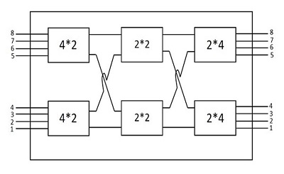
The multistage switch like the above one needs less number of Crosspoints than the ones needed in Crossbar switching. According to the example shown above, for the 8 (input) and 8 (output) various subscribers (both called and calling subscribers), the Crosspoints needed in a normal Crossbar network will be square of them, which is 64. However, in the multistage Crossbar network, just 40 Crosspoints are enough. This is as shown in the diagram above. In a large multistage Crossbar switch, the reduction is more significant.
Advantages of a Multistage Network
The advantages of a multistage network are as follows −
- The number of Crossbars are reduced.
- The number of paths of connection can be more.
Disadvantages of a Multistage Network
The disadvantage of a multistage network are as follows −
Multistage switches may cause Blocking.
The number or size of the intermediate switches if increased can solve this problem, but the cost increases with this.
Blocking
Blocking reduces the number of Crosspoints. The following diagram will help you understand Blocking in a better way.
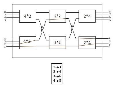
In the above figure, where there are 4 inputs and 2 outputs, the Subscriber 1 was connected to Line 3 and the Subscriber 2 was connected to Line 4. The red-colored lines indicate the connections. However, there will be more requests coming; a calling request from subscriber 3 and subscriber 4 if made cannot be processed, as the call cannot be established.
The subscribers of the above block also (as shown in the above diagram) face the same problem. Only two blocks can be connected at a time; connecting more than two or all of the inputs cannot be done (as it depends on the number of outputs present). Hence, a number of connections cannot be established simultaneously, which is understood as the calls being blocked up.
TSSN - Switching Techniques
In this chapter, we will discuss the switching techniques in Telecommunication Switching Systems and Networks.
In large networks, there may be more than one path for transmitting data from the sender to the receiver. Selecting a path that data must take out of the available options can be understood as Switching. The information may be switched while it travels between various communication channels.
There are three typical switching techniques available for digital traffic. They are −
- Circuit Switching
- Message Switching
- Packet Switching
Let us now see how these techniques work.
Circuit Switching
In Circuit switching, two nodes communicate with each other over a dedicated communication path. In this, a circuit is established to transfer the data. These circuits may be permanent or temporary. Applications that use circuit switching may have to go through three phases. The different phases are −
- Establishing a circuit
- Transferring the data
- Disconnecting the circuit
The following figure below shows the pattern of Circuit switching.
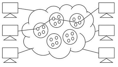
Circuit switching was designed for voice applications. Telephone is the best suitable example of circuit switching. Before a user can make a call, a virtual path between the called subscriber and the calling subscriber is established over the network.
The drawbacks of circuit switching are −
- The waiting time lasts long, and there is no data transfer.
- Each connection has a dedicated path, and this gets expensive.
- When connected systems do not use the channel, it is kept idle.
The circuit pattern is made once the connection is established, using the dedicated path which is intended for data transfer, in the circuit switching. The telephone system is a common example of Circuit Switching technique.
Message Switching
In message switching, the whole message is treated as a data unit. The data is transferred in its entire circuitry. A switch working on message switching, first receives the whole message and buffers it until there are resources available to transfer it to the next hop. If the next hop is not having enough resource to accommodate large size message, the message is stored and the switch waits.
The following figure shows the pattern of Message switching.
In this technique, the data is stored and forwarded. The technique is also called the Store-and-Forward technique. This technique was considered a substitute to circuit switching. But the transmission delay that followed the end to end delay of message transmission added to the propagation delay and slowed down the entire process.
Message switching has the following drawbacks −
Every switch in the transit path needs enough storage to accommodate the entire message.
Because of the waiting included until resources are available, message switching is very slow.
Message switching was not a solution for streaming media and real-time applications.
The data packets are accepted even when the network is busy; this slows down the delivery. Hence, this is not recommended for real time applications like voice and video.
Packet Switching
The packet switching technique is derived from message switching where the message is broken down into smaller chunks called Packets. The header of each packet contains the switching information which is then transmitted independently. The header contains details such as source, destination and intermediate node address information. The intermediate networking devices can store small size packets and dont take many resources either on the carrier path or in the internal memory of switches.
Individual routing of packets is done where a total set of packets need not be sent in the same route. As the data is split, bandwidth is reduced. This switching is used for performing data rate conversion.
The figure below shows the pattern of Packet switching.
The following figure shows the pattern of Packet switching.
The line efficiency of packet switching can be enhanced by multiplexing the packets from multiple applications over the carrier. The internet which uses this packet switching enables the user to differentiate data streams based on priorities. Depending upon the priority list, these packets are forwarded after storing to provide quality of service.
The packet switching technique was proved to be an efficient technique and is being widely used in both voice and data transfer. The transmission resources are allocated using different techniques such as Statistical Multiplexing or Dynamic Bandwidth allocation.
Statistical Multiplexing
Statistical multiplexing is a communication link sharing technique, which is used in packet switching. The shared linking is variable in statistical multiplexing, whereas it is fixed in TDM or FDM. This is a strategic application for maximizing the utilization of bandwidth. This can increase the efficiency of network, as well.
By allocating the bandwidth for channels with valid data packets, statistical multiplexing technique combines the input traffic to maximize channel efficiency. Each stream is divided into packets, and delivered on a first-come, first-served basis. The increase in priority levels allow to allocate more bandwidth. The time slots are taken care not to be wasted in the statistical multiplexing whereas they are wasted in time division multiplexing.
Network Traffic
As the name implies, network traffic is simply the data that moves along the network in a given time. The data transmission is done in the form of packets, where the number of packets transmitted per unit time is considered as load. The controlling of this network traffic includes managing, prioritizing, controlling or reducing the network traffic. The amount and type of traffic on a network can also be measured with the help of a few techniques. The network traffic needs to be monitored as this helps in network security; high data rate might cause damage to the network.
A measure of the total work done by a resource or facility, over a period (usually 24 hours) is understood as Traffic Volume and is measured in Erlang-hours. The traffic volume is defined as the product of the average traffic intensity and the period of
$$Traffic \:\: volume = Traffic \: Intensity \times Time\: period$$
Congestion
Congestion in a network is said to have occurred when load on the network is greater than the capacity of the network. When the buffer size of the node exceeds the data received, then the traffic will be high. This further leads to congestion. The amount of data moved from a node to the other can be called as Throughput.
The following figure shows congestion.
In the above figure, when the data packets arrive at Node from the senders A, B and C then the node cannot transmit the data to the receiver at a faster rate. There occurs a delay in transmission or may be data loss due to heavy congestion.
When too many packets arrive at the port in a packet switched network, then the performance degrades and such a situation is called Congestion. The data waits in the queue line for transmission. When the queue line is utilized more than 80%, then the queue line is said to be congested. The Congestion control techniques help in controlling the congestion. The following graph, drawn between throughput and packet send shows the difference between congestion controlled transmission and uncontrolled transmission.
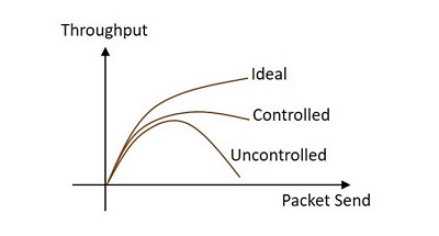
The techniques used for congestion control are of two types open loop and closed loop. The loops differ by the protocols they issue.
Open Loop
The open loop congestion control mechanism produces protocols to avoid congestion. These protocols are sent to the source and the destination..
Closed Loop
The closed loop congestion control mechanism produces protocols that allow the system to enter the congested state and then detect and remove the congestion. The explicit and implicit feedback methods help in the running of the mechanism.
TSSN - Time Division Switching
In this chapter, we will discuss the switching techniques in Telecommunication Switching Systems and Networks.
In large networks, there may be more than one path for transmitting data from the sender to the receiver. Selecting a path that data must take out of the available options can be understood as Switching. The information may be switched while it travels between various communication channels.
There are three typical switching techniques available for digital traffic. They are −
- Circuit Switching
- Message Switching
- Packet Switching
Let us now see how these techniques work.
Circuit Switching
In Circuit switching, two nodes communicate with each other over a dedicated communication path. In this, a circuit is established to transfer the data. These circuits may be permanent or temporary. Applications that use circuit switching may have to go through three phases. The different phases are −
- Establishing a circuit
- Transferring the data
- Disconnecting the circuit
The following figure below shows the pattern of Circuit switching.
Circuit switching was designed for voice applications. Telephone is the best suitable example of circuit switching. Before a user can make a call, a virtual path between the called subscriber and the calling subscriber is established over the network.
The drawbacks of circuit switching are −
- The waiting time lasts long, and there is no data transfer.
- Each connection has a dedicated path, and this gets expensive.
- When connected systems do not use the channel, it is kept idle.
The circuit pattern is made once the connection is established, using the dedicated path which is intended for data transfer, in the circuit switching. The telephone system is a common example of Circuit Switching technique.
Message Switching
In message switching, the whole message is treated as a data unit. The data is transferred in its entire circuitry. A switch working on message switching, first receives the whole message and buffers it until there are resources available to transfer it to the next hop. If the next hop is not having enough resource to accommodate large size message, the message is stored and the switch waits.
The following figure shows the pattern of Message switching.
In this technique, the data is stored and forwarded. The technique is also called the Store-and-Forward technique. This technique was considered a substitute to circuit switching. But the transmission delay that followed the end to end delay of message transmission added to the propagation delay and slowed down the entire process.
Message switching has the following drawbacks −
Every switch in the transit path needs enough storage to accommodate the entire message.
Because of the waiting included until resources are available, message switching is very slow.
Message switching was not a solution for streaming media and real-time applications.
The data packets are accepted even when the network is busy; this slows down the delivery. Hence, this is not recommended for real time applications like voice and video.
Packet Switching
The packet switching technique is derived from message switching where the message is broken down into smaller chunks called Packets. The header of each packet contains the switching information which is then transmitted independently. The header contains details such as source, destination and intermediate node address information. The intermediate networking devices can store small size packets and dont take many resources either on the carrier path or in the internal memory of switches.
Individual routing of packets is done where a total set of packets need not be sent in the same route. As the data is split, bandwidth is reduced. This switching is used for performing data rate conversion.
The figure below shows the pattern of Packet switching.
The following figure shows the pattern of Packet switching.
The line efficiency of packet switching can be enhanced by multiplexing the packets from multiple applications over the carrier. The internet which uses this packet switching enables the user to differentiate data streams based on priorities. Depending upon the priority list, these packets are forwarded after storing to provide quality of service.
The packet switching technique was proved to be an efficient technique and is being widely used in both voice and data transfer. The transmission resources are allocated using different techniques such as Statistical Multiplexing or Dynamic Bandwidth allocation.
Statistical Multiplexing
Statistical multiplexing is a communication link sharing technique, which is used in packet switching. The shared linking is variable in statistical multiplexing, whereas it is fixed in TDM or FDM. This is a strategic application for maximizing the utilization of bandwidth. This can increase the efficiency of network, as well.
By allocating the bandwidth for channels with valid data packets, statistical multiplexing technique combines the input traffic to maximize channel efficiency. Each stream is divided into packets, and delivered on a first-come, first-served basis. The increase in priority levels allow to allocate more bandwidth. The time slots are taken care not to be wasted in the statistical multiplexing whereas they are wasted in time division multiplexing.
Network Traffic
As the name implies, network traffic is simply the data that moves along the network in a given time. The data transmission is done in the form of packets, where the number of packets transmitted per unit time is considered as load. The controlling of this network traffic includes managing, prioritizing, controlling or reducing the network traffic. The amount and type of traffic on a network can also be measured with the help of a few techniques. The network traffic needs to be monitored as this helps in network security; high data rate might cause damage to the network.
A measure of the total work done by a resource or facility, over a period (usually 24 hours) is understood as Traffic Volume and is measured in Erlang-hours. The traffic volume is defined as the product of the average traffic intensity and the period of
$$Traffic \:\: volume = Traffic \: Intensity \times Time\: period$$
Congestion
Congestion in a network is said to have occurred when load on the network is greater than the capacity of the network. When the buffer size of the node exceeds the data received, then the traffic will be high. This further leads to congestion. The amount of data moved from a node to the other can be called as Throughput.
The following figure shows congestion.
In the above figure, when the data packets arrive at Node from the senders A, B and C then the node cannot transmit the data to the receiver at a faster rate. There occurs a delay in transmission or may be data loss due to heavy congestion.
When too many packets arrive at the port in a packet switched network, then the performance degrades and such a situation is called Congestion. The data waits in the queue line for transmission. When the queue line is utilized more than 80%, then the queue line is said to be congested. The Congestion control techniques help in controlling the congestion. The following graph, drawn between throughput and packet send shows the difference between congestion controlled transmission and uncontrolled transmission.
The techniques used for congestion control are of two types open loop and closed loop. The loops differ by the protocols they issue.
Open Loop
The open loop congestion control mechanism produces protocols to avoid congestion. These protocols are sent to the source and the destination..
Closed Loop
The closed loop congestion control mechanism produces protocols that allow the system to enter the congested state and then detect and remove the congestion. The explicit and implicit feedback methods help in the running of the mechanism.
TSSN - Telephone Networks
In this chapter, we will learn about the Public Switched Telephone Network (PSTN). This extraordinary telecommunication network is counted as one of the achievements in the field of technology advancement. However, there come a few problems when we come to these networks. We will discuss these problems in our subsequent sections.
PSTN
The Public Switched Telephone Network is understood as an aggregate of worlds circuit switched telephone networks, used for providing public telecommunication. The PSTN networks are called POTS (Plain Old Telephone Systems). These networks are operated regionally, locally, nationally and inter-nationally using telephone lines, fiber optic cables, microwave transmission links or cellular communications.
PSTN consists of switches at centralized points on the network, which act as nodes for communication between any point and any other point on the network. All the types of Switching techniques discussed previously, such as circuit switching, packet switching and message switching are different modes of using PSTN.
Subscriber Loop Systems
In a general telephone network, every subscriber has two dedicated lines connecting to the nearest switching exchange, which are called the Loop lines of that subscriber. The laying of lines to the subscriber premises from the exchange office is called Cabling. As it is difficult to run cables from each subscribers premises to the exchange, large cables are used through which the drop wires (subscriber lines) are taken to a distribution point.
The drop wires are connected to wire pairs at the distribution point, in the cables. Such distribution cables from nearby geographical area are connected at a same feeder point where they connected to branch feeder cables which in turn, are connected to the main feeder cable. This whole process can be understood with the help of the following figure
The subscriber cable pairs from the exchange will also terminate at MDF through main feeder cables that carry large number of wire pairs. These subscriber pairs and exchange pairs are interconnected at the MDF using jumpers, which makes MDF to provide flexible mechanism for reallocating cable pairs and subscriber numbers. This means a subscriber who shifts to a different location though in the same exchange area, can be allowed to use the same number using appropriate jumper, while his old drop wires can be used by another subscriber with a new number.
Switching Hierarchy and Routing
The next important system in this is the switching hierarchy and routing of the telephone lines. The interconnectivity of calls between different areas having different exchanges is done with the help of trunk lines between the exchanges. The group of trunk lines that are used to interconnect different exchanges are called the Trunk Groups.
In the process of interconnecting exchanges, there are three basic topologies, such as
- Mesh Topology
- Star Topology
- Hierarchical
Mesh Topology
Mesh topology, as the name implies, is a fully connected network. The number of trunk groups in a mesh network is proportional to the square of the exchanges being interconnected. Hence, these mesh topologies are widely used in metropolitan areas where there is heavy traffic.
The following figure shows how a mesh topology looks like.
Star Topology
Star topology is connected in the shape of a star, which utilizes an intermediate exchange called a tandem exchange through which all other exchanges communicate. The figure given below shows the model of a star network. The star network is used when traffic levels are comparatively low. Many star networks can be used by interconnecting through additional tandem exchange, leading to a two-level star network as shown in the following figure.
Hierarchical
The hierarchical topology is used to handle heavy traffic with minimal number of trunk groups. The traffic flows through the Final route which is the highest level of hierarchy. If the traffic intensity between any pair of exchanges is high, direct trunk routes may be established between them as indicated by dashed lines in the figure given below. These direct trunk routes are High Usage routes. Wherever these high usage routes exist, the traffic flows through them. Here, the overflown traffic is routed along the hierarchical path. No overflow traffic is permitted from the final route.
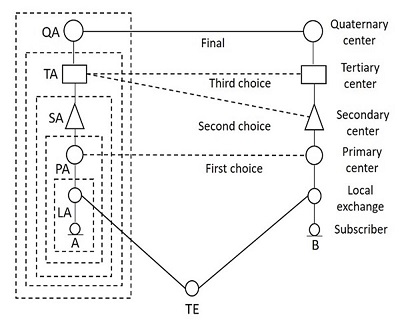
To decide the routing on a particular connection, the following three methods are used −
- Right-through routing
- Own-exchange routing
- Computer-controlled routing
Transmission Plan
The Transmission of signals through cables should be high in quality in order to ensure better communication. The transmission links between national and international circuits should be better to connect in tandem for establishing calls.
To have high quality standards, the following guidelines were put forward by the CCITT −
The maximum number of circuits to be used in an international call is 12.
No more than four international circuits be used in tandem between the originating and the terminating international switching centers.
In exceptional cases and for a low number of calls, the total number of circuits may be 14, but even in this case, the international circuits are limited to a maximum of four.
Along with limiting the number of circuits required, the losses such as line loss or wire loss and switch loss or contact loss should also be minimized. These aspects come under the transmission loss budget, which provides for factors such as keeping echo levels within limits and control singing.
Because of the long distances, the circuits need amplifiers and repeaters at appropriate intervals to boost the signals. At the subscriber-line interfaces, mismatch occurs; this results in reflecting a part of the incoming signal onto the outgoing circuit, which returns to the speaker as Echo. The echo suppressor or cancellation circuits are used to minimize the effect of the echo. The signal attenuation and echo are the main losses in the transmission lines along with contact and wire losses.
Transmission Systems
There are different types of transmission systems such as Radio systems, Coaxial cable systems and Optical fiber systems being the prominent ones. As the length of the transmission distance increases, the mode of transmission also gets changed.
The signal transmission advanced from wire transmission to wireless transmission. The Radio systems provide wireless transmission, the coaxial cable systems allow transmission of signal through wire and the fiber optic systems provide communication through optical fibers.
Depending upon the mechanism of signal propagation, the Radio communication has four varieties of communication, such as −
- Skywave or Ionospheric Communication
- Line-of-sight (LOS) microwave communication limited by horizon
- Tropospheric Scatter Communication
- Satellite Communication
Numbering Plan
During the early stages of development, the numbering scheme was confined to a small single exchange, which used to connect to the other exchanges by identifying them with the names of the towns in which they were located. But with the increase in the number of subscribers, many exchanges were introduced.
A large central exchange which serves the main business center of a town, can be called the Main Exchange and the smaller exchanges serving different localities are called the Satellite Exchanges. The area containing the complete network of the main exchange and the satellites is known as the Multi-exchange area. A common numbering scheme was required to identify the location of the exchange of called subscriber, especially when the call is from a location outside the Multi-exchange area.
The common numbering scheme is called the Linked Numbering Scheme, where all the exchanges in a town were collectively identified by the name of the town. With the introduction of Subscriber Trunk Dialing (STD) or Direct Distance Dialing (DDD) for inter-city and inter-town long distance communications, the Multi-exchange areas were also allotted unique identification number. In order to make very long distance communications possible, the international dialing called the International Subscriber Dialing (ISD) was introduced, where the international numbering plan and national numbering plan came into existence.
Types of Numbering Plans
In this section, we will discuss the Numbering Plans for telephone networks. The plans are described in brief below −
Open Numbering Plan
This is also called the Non-Uniform Numbering Plan and it permits wide variation in the number of digits to be used to identify a subscriber within a multi-exchange area or within a country.
Semi-Open Numbering Plan
This plan permits number lengths to differ by almost one or two digits. The semi-open numbering plan is commonly used in countries such as India, Sweden, Switzerland and UK.
Closed Numbering Plan
This is also called the Uniform Numbering Plan where the number of digits in a subscriber number are fixed. This is used in a few countries such as France, Belgium, Canada, Hawaii and in a few parts of USA.
An International Numbering Plan or World Numbering Plan has been defined by the CCITT. For numbering purposes, the world is divided into zones. The following figure indicates the telephone number structure.
A national number consists of three parts. The parts are described below −
The Area Code or the Trunk Code
This code identifies a particular numbering area or the multi-exchange area of the called subscriber. It is with this code, the routing for a trunk call is determined and charged for it.
Exchange Code
This code identifies a particular exchange within a numbering area. It determines the routing for incoming trunk call from another numbering area or for a call originating from one exchange and destined to another in the same numbering area.
Subscriber Line Number
It is used to select the called subscriber line at the terminating exchange. The combination of the exchange code and the subscriber line number is called the Subscriber Line number in CCITT terminology.
Charging Plan
The calls are charged as accounted by the metering instrument connected to each subscriber line or as per a metering register that is assigned to each subscriber in case of electronic exchanges. A meter counts the number of charging units, and that count is incremented by sending a pulse to the meter. For the number of units, the meter reads, a bill is raised by assigning a rate to the charging unit.
The individual calls can be charged based on the following categories.
- Duration independent charging
- Duration dependent charging
Local calls within a numbering area are usually charged on a duration independent basis. For duration dependent charging, the meter starts incrementing, once the called subscriber answers the call. Depending upon the number of exchanges involved in setting up a call, more than one pulse is sent to the charging meter, which is called Multi-Metering. The metering pulse rate keeps on increasing per min with the distance between the called and the calling subscribers.
TSSN - Signaling Techniques
Signaling techniques enable the circuit to function as a whole by inter connecting all varieties of switching systems. There are three forms of signaling involved in a telecommunication network.
- Subscriber loop signaling
- Intraexchange or register signaling
- Interexchange or inter-register signaling
The subscriber loop signaling depends upon the type of telephone instrument used. The intra exchange signaling refers to the internal portion of a switching system that is heavily dependent upon the type and design of a switching system, which varies depending upon the model. The inter-exchange signaling takes place between exchanges. This helps in the exchange of address digits, which pass from exchange to exchange on a link-by-link basis. The network-wide signaling that involves end-to-end signaling between the originating exchange and the terminating exchange is called the Line signaling.
The two main types of signaling techniques are −
In-Channel Signaling
In-Channel Signaling is also known as Per Trunk Signaling. This uses the same channel, which carries user voice or data to pass control signals related to that call or connection. No additional transmission facilities are needed, for In-channel signaling.
Common Channel Signaling
Common Channel Signaling uses a separate common channel for passing control signals for a group of trunks or information paths. This signaling does not use the speech or the data path for signaling.
We will discuss the signaling techniques in depth in our subsequent sections.
Types of Signaling Techniques
As discussed above, the signaling techniques are categorized into two, the In-channel signaling and the Common channel signaling. However, these are further divided into few types depending upon the frequencies and frequency techniques used.
The division is as shown in the following figure −
In-channel Signaling
This type of signaling is used to carry voice or data and pass control signals related to a call or connection. There are different types of In-channel Signaling, as seen in the above figure. The D.C. signaling is simple, cheap and reliable even for unamplified audio circuits. However, for amplified audio circuits, low frequency A.C. signaling may be adopted.
The Voice Frequency signaling is used when FDM (Frequency Division Multiplexing) transmission systems are used, because low frequency signaling and D.C. signaling cannot be provided. This Voice Frequency signaling may be In-band or Out-band.
In-band Signaling
In-band voice frequency uses the same frequency band as the voice, which is 300-3400 Hz, which has to be protected against false operation by speech. One such instant took place when a ladys voice which has generated a tone at around 2600Hz lasting for a duration of 100ms was detected as the line disconnect signal due to which her calls were frequently being disconnected in the middle of her conversation. Such problems precluded the in-band signaling during speech phase.
The advantages of In-band signaling are −
The control signals can be sent to every part where a speech signal can reach.
The control signals will be independent of the transmission systems as they are carried along with the speech signals.
The Analog to digital and Digital to analog conversion processes will not affect them.
Out-band Signaling
The out-band signaling uses frequencies which are above the voice band but below the upper limit of 4000 Hz of the nominal voice channel spacing. The signaling is done throughout the speech period and thus continuous supervision of the call is allowed. Extra circuits are needed to handle the extremely narrow band width of this signaling, due to which it is seldom used. Both of these in-band and out-band voice frequency signaling techniques have limited information transmission capacity. In order to provide enhanced facilities, common channel signaling is used.
Common Channel Signaling
Common Channel Signaling uses a separate common channel for passing control signals for a group of trunks or information paths as it does not use the speech or the data path for signaling. The common channel signaling consists of two types of nodes such as Signaling Transfer Points (STP) and Signaling Points (SP).
A Signaling point is capable of handling control messages directly addressed to it but is incapable of routing messages. Signaling transfer point is capable of routing messages and can perform the functions of SP.
This common channel signaling is implemented in two modes −
- Channel associated mode
- Channel non-associated mode
Channel-associated Mode
In the channel-associated mode, the channel closely tracks the trunk groups along the entire length of the connection. Here, the signaling is done on a separate channel; the signaling path passes through the same set of switches, as does the speech path.
The following figure shows the associated mode of operation in common channel signalling

The signaling paths for the speech paths A-B, A-C-B and B-D are A-B, A-C-B and B-D respectively. The advantages of this signaling are −
The implementation is economic
The assignment of trunk groups is simple
Channel Non-associated Mode
In the channel non-associated mode, there is no close or simple assignment of the control channels to trunk groups. It follows a different path from that of the speech signal as shown in the following figure.
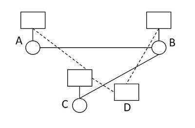
The signaling paths for the speech paths A-B and B-C are A-C-D-B and B-D-C respectively. The network topologies are different for signaling and speech networks. Though this scheme offers flexibility as there is no switching center, it is a bit complex, as the signal messages may be transferred between the two end switching systems via any available path in the common channel signaling network according to its own routing principles.
Private Branch Exchange (PBX)
Private Branch Exchange or PBX can be understood as a local exchange within an office or a building, in order to communicate within themselves. As the name implies, it is a private exchange, which is a branch to the main exchange similar to a local loop connected to the main loop as a branch.
Private Branch Exchange is a telephone system within a local area that switches calls between those users on local lines while allowing all users to share a certain number of external phone lines. The main purpose of PBX is to save the cost of requirement for a line to each user to the central exchange office.
The following figure shows the model of a PBX.
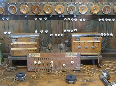
The above figure shows an early model of the PBX system. The PBX is usually operated and owned by the local office where the users are connected through it within that limited area.
The parts of a PBX include −
A telephone trunk that contains many phone lines, which are terminated at PBX.
A computer that handles the incoming and outgoing calls of PBX along with switching between different calls within the local loop.
The network of lines within the PBX.
A human operator console, which is optional.
Having all these along with the PBX equipment, the local branch exchange is built. The PBX exchanges previously operated using the analog technology. However, these exchanges operate on digital technology. The digital signals are converted to analog for outside calls on the local loop using Plain Old Telephone Services (POTS).
TSSN - ISDN
In this chapter, we will learn about the Integrated Services Digital Network. Earlier, the transmission of data and voice both were possible through normal POTS, Plain Old Telephone Systems. With the introduction of Internet came the advancement in telecommunication too. Yet, the sending and receiving of data along with voice was not an easy task. One could use either the Internet or the Telephone. The invention of ISDN helped mitigate this problem.
The process of connecting a home computer to the Internet Service Provider used to take a lot of effort. The usage of the modulator-demodulator unit, simply called the MODEM was the essential thing to establish a connection. The following figure shows how the model worked in the past.
The above figure shows that the digital signals have to be converted into analog and analog signals to digital using modem during the whole path. What if the digital information at one end reaches to the other end in the same mode, without all these connections? It is this basic idea that lead to the development of ISDN.
As the system has to use the telephone cable through the telephone exchange for using the Internet, the usage of telephone for voice calls was not permitted. The introduction of ISDN has resolved this problem allowing the transmission of both voice and data simultaneously. This has many advanced features over the traditional PSTN, Public Switched Telephone Network.
ISDN
ISDN was first defined in the CCITT red book in 1988.The Integrated Services of Digital Networking, in short ISDN is a telephone network based infrastructure that allows the transmission of voice and data simultaneously at a high speed with greater efficiency. This is a circuit switched telephone network system, which also provides access to Packet switched networks.
The model of a practical ISDN is as shown below.
ISDN supports a variety of services. A few of them are listed below −
- Voice calls
- Facsimile
- Videotext
- Teletext
- Electronic Mail
- Database access
- Data transmission and voice
- Connection to internet
- Electronic Fund transfer
- Image and graphics exchange
- Document storage and transfer
- Audio and Video Conferencing
- Automatic alarm services to fire stations, police, medical etc.
Types of ISDN
Among the types of several interfaces present, some of them contains channels such as the B-Channels or Bearer Channels that are used to transmit voice and data simultaneously; the D- Channels or Delta Channels that are used for signaling purpose to set up communication.
The ISDN has several kinds of access interfaces such as −
- Basic Rate Interface (BRI)
- Primary Rate Interface (PRI)
- Narrowband ISDN
- Broadband ISDN
Basic Rate Interface (BRI)
The Basic Rate Interface or Basic Rate Access, simply called the ISDN BRI Connection uses the existing telephone infrastructure. The BRI configuration provides two data or bearer channels at 64 Kbits/sec speed and one control or delta channel at 16 Kbits/sec. This is a standard rate.
The ISDN BRI interface is commonly used by smaller organizations or home users or within a local group, limiting a smaller area.
Primary Rate Interface (PRI)
The Primary Rate Interface or Primary Rate Access, simply called the ISDN PRI connection is used by enterprises and offices. The PRI configuration is based on T-carrier or T1 in the US, Canada and Japan countries consisting of 23 data or bearer channels and one control or delta channel, with 64kbps speed for a bandwidth of 1.544 M bits/sec. The PRI configuration is based on E-carrier or E1 in Europe, Australia and few Asian countries consisting of 30 data or bearer channels and two-control or delta channel with 64kbps speed for a bandwidth of 2.048 M bits/sec.
The ISDN BRI interface is used by larger organizations or enterprises and for Internet Service Providers.
Narrowband ISDN
The Narrowband Integrated Services Digital Network is called the N-ISDN. This can be understood as a telecommunication that carries voice information in a narrow band of frequencies. This is actually an attempt to digitize the analog voice information. This uses 64kbps circuit switching.
The narrowband ISDN is implemented to carry voice data, which uses lesser bandwidth, on a limited number of frequencies.
Broadband ISDN
The Broadband Integrated Services Digital Network is called the B-ISDN. This integrates the digital networking services and provides digital transmission over ordinary telephone wires, as well as over other media. The CCITT defined it as, Qualifying a service or system requiring transmission channels capable of supporting rates greater than primary rates.
The broadband ISDN speed is around 2 MBPS to 1 GBPS and the transmission is related to ATM, i.e., Asynchronous Transfer Mode. The broadband ISDN communication is usually made using the fiber optic cables.
As the speed is greater than 1.544 Mbps, the communications based on this are called Broadband Communications. The broadband services provide a continuous flow of information, which is distributed from a central source to an unlimited number of authorized receivers connected to the network. Though a user can access this flow of information, he cannot control it.
Advantages of ISDN
ISDN is a telephone network based infrastructure, which enables the transmission of both voice and data simultaneously. There are many advantages of ISDN such as −
- As the services are digital, there is less chance for errors.
- The connection is faster.
- The bandwidth is higher.
- Voice, data and video − all of these can be sent over a single ISDN line.
Disadvantages of ISDN
The disadvantage of ISDN is that it requires specialized digital services and is costlier.
However, the advent of ISDN has brought great advancement in communications. Multiple transmissions with greater speed are being achieved with higher levels of accuracy.