- TSSN - Home
- TSSN - Introduction
- TSSN - Switching Systems
- Elements of a Switching System
- TSSN - Strowger Switching System
- TSSN - Switching Mechanisms
- TSSN - Common Control
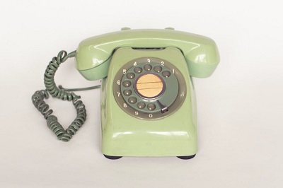
- TSSN - Touch-tone Dial Telephone
- TSSN - Crossbar Switching
- Crossbar Switch Configurations
- TSSN - Crosspoint Technology
- TSSN - Stored Program Control
- TSSN - Software Architecture
- TSSN - Switching Techniques
- TSSN - Time Division Switching
- TSSN - Telephone Networks
- TSSN - Signaling Techniques
- TSSN - ISDN
TSSN - Switching Mechanisms
In this chapter, we will discuss the switching mechanisms in Telecommunication Switching Systems and Networks.
In our previous chapters, we discussed the mechanism in the telephone set. Let us now see what happens when this telephone set sends a signal to the switching system. The switching system at the exchange should be able to connect the line automatically to the called subscriber. In the Strowger switching system, there are two types of selectors; these selectors form the building blocks for the switching systems.
- Uni-selector
- Two-motion selector
Both of these selectors are constructed using electro-mechanical rotary switches. The Uni-selector has a single selector pole and multiple throws to reach the bank of contacts for each number dialed. The two-motion selector has two rotary switches for vertical and horizontal stepping movement, to reach the bank of contacts.
Uni-selector Switching
The Uni-selector switching mechanism consists of an Electromagnet, an Armature with springs, a Pawl, a ratchet wheel with wiper attached and a detent. The wiper is made to move on the bank contacts in clock-wise direction. As the wiper moves in one-direction, the process is called Uni-selector switching. The contacts onto which the wiper moves are called Bank contacts as a number of contacts are placed in this shape of an arc.
The following figure shows the drive mechanism of the Uni-selector Strowger switching system.
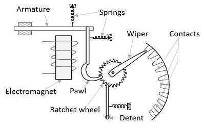
When the input voltage energizes the Electromagnet, the armature is pulled down towards the magnet. Now as the armature gets attracted towards the electromagnet, the pawl falls one position down the previous one in the ratchet wheel. The detent prevents the movement of the ratchet wheel.
Once the electromagnet gets de-energized, the armature is released and this action moves the pawl upwards, which further moves the ratchet wheel to one position above. Hence, the wiper moves one position below or in clockwise direction, to make a contact. If the electromagnet is energized and de-energized five times, by applying five pulses, the wiper moves by five contacts. Usually three sets (or more) of wipers are placed associated with the banks of Uni-selector, one for each bank. The sets are rigidly mounted to a wiper assembly, which moves whenever the ratchet wheel rotates. The interrupter spring releases the magnet and enables it to make another step.
The following figure shows a practical Uni-selector Strowger switching system.
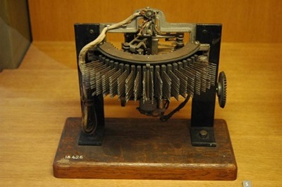
The type of switching mechanism discussed here is known as the reverse drive type because, here the ratchet wheel moves when the armature return to its rest position. If it is arranged such that the wheel moves during the forward motion of the armature it is known as the forward drive type. The Reverse drive type mechanism is prevalent in uni-selectors and the forward drive type mechanism in the two-motion selectors.
There is an interrupter contact associated with the Uni-selector, which is normally closed. When the armature is energized, the interrupter contact opens and allows the movement of armature, which helps the armature return to its rest position after breaking up the armature energizing circuit.
Two-motion Selectors
Unlike in Uni-selector, the motion in these selectors is two-way, vertical and horizontal. An upward movement is made in vertical and horizontal directions; there are no contacts made in the vertical movement. However, bank contacts are made in the horizontal movement. If the two-motion selector has 10 levels, each having 10 contacts, then 100 contacts are accessible, by the vertical and horizontal movement of the two-motion selector switching system.
The following figure shows the internal structure of two-motion switching selectors.
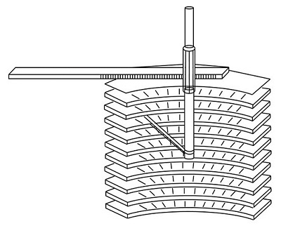
When the first digit is dialed, the pulses energize and de-energize the vertical magnet according to the number dialed, with the help of ratchet and pawl mechanism. This is called as Vertical Stepping.
When the second digit is dialed, the dialing pulses are diverted to horizontal magnet, with the help of a relay where the pulses energize and de-energize the horizontal magnet according to the number dialed, with the help of ratchet and pawl mechanism. This is called Horizontal Stepping.
Normally, there are 11 vertical positions and 11 horizontal contacts in each vertical position. The lowest vertical position and the first horizontal contact in each vertical level are home positions, and the remaining ones are actual switching positions. Thus, the wiper in a two-motion selector has access to 100 switching contacts. The following figure shows a practical two-motion switching selector.
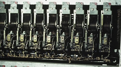
Thus, the wiper assembly establishes the call; after completion of which it comes back to the home position. For this purpose, the rotary magnet is operated by the current and thus the wiper assembly moves through the remaining contacts of the level. A restoring spring forces the wiper assembly to drop vertically and then return horizontally to the home position.
Step-by-Step Switching
The Step-by-step switching system is a very popular and widely-used switching system, which may be constructed using Uni-selectors or two-motion selectors or the combination of both. The wiper present in this switching, steps forward by one contact and then moves forward according to the number of dialed pulses or according to the signaling conditions and hence the name, step-by-step switching is given.
A step-by-step switching is also called the Direct control system as the relevant signaling tones are sent out to the subscriber by the switching elements or selectors at the appropriate stages of switching. This system has three main stages of configuration. The following figure shows the different stages.
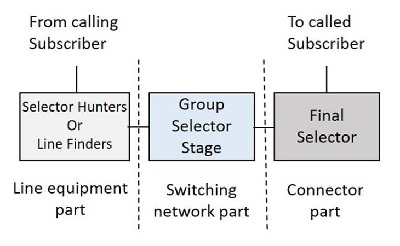
Let us now see how these blocks function.
Selector Hunters
As soon as the calling subscriber gets ready to dial the number, by lifting the handset from the telephone, a dial tone is heard. We have already learnt that a number is not accepted unless the dial tone is heard. But to get that dial tone, the line has to be established when the handset is lifted up. The Selector Hunter circuit, establishes the line to make a call as immediately as the calling subscriber lifts up the handset to make a call.

The Selector Hunters hunt for selecting a switching matrix part. Usually, 24-outlet Uni-selectors are used as selector hunters. and so this can be called as Subscriber Uni-selector scheme as there is a dedicated Uni-selector for each subscriber in the system. These can also be build using two-motion selectors.
The selector hunter mechanism can also be replaced with the line finder mechanism, where there is small difference between the two in construction. Here, we shall discuss the selector hunter mechanism. The figure below gives an idea about its construction.
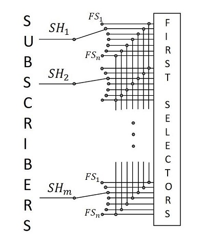
When a calling subscriber lifts the handset to make a call, the selector hunter activates the interrupter mechanism, which steps up the wiper until a free first group selector is found at the outlet. One of the bank contacts of the selector hunter, at this point, senses whether the first group selector is free or busy. Once a free first selector is sensed, the interrupter is disabled and the connection is established, where the first selector sends out a dialer tone to the calling subscriber.
The line finder approach is used where the traffic is low and the exchange is small, whereas the selector hunter mechanism described above is used for large exchanges with heavy traffic and this approach is cost-effective.
Group Selector Stage
The Group Selector stage has the main switching network. The calling subscriber dials the number after hearing the dial tone. The first number when dialed activates the first selector. To be more precise, the group selector consists of certain selector stages. We used to have 5 numbers as an identification number, for the land connection. Hence, there were three selector stages present.
To dial the first number, the number plate is rotated by placing the finger in the finger gap given according to the subscriber number. After taking out the finger, the number plate is rotated back to its previous position, which sends the dialing pulses to the first selector. The first selector then moves accordingly, to place a contact.
When the subscriber starts dialing, the dial tone produced till then, cuts off and the pulse train is received according to the number dialed. The wiper assembly of the first selector then moves vertically upward, according to the number dialed. The wipers then move in the horizontal plane across the contacts until they come across a contact to which a free second group selector is connected. This horizontal stepping is completed within the inter-digit gap of about 240ms. From there, the first group selector connects the electrical path to the available second group selector.
Likewise, every group selector connects path according to the number dialed and then extends the connection to the next selector until the final selector. The action of the final selector is a bit different. As discussed above, three selectors are present and the fourth and the fifth numbers are connected to the matrix by the final selector.
Final Selector
The last two digits are processed by the final selector. This selector moves vertically according to the fourth digit dialed and then it moves horizontally according to the last digit, as there are no further digits to connect it to some other connector. The last digit dialed, establishes electrical connection to the called subscriber.
Since the final selector responds to both the digits in vertical and horizontal directions unlike the group selectors, this final selector is also called a Numerical Selector. If the called subscriber is free, as sensed from a signal at the corresponding bank contact, the final selector sends out a ringing current to the called subscriber and a ringing tone to the calling subscriber.

When the called subscriber lifts his handset, the ringing current and the ringing tone provided till then, are cut off and the call metering circuits are enabled by the control circuits associated with the final selectors. Otherwise, if the called subscriber is found to be busy on some other line, then the final selector sends out a busy tone to the calling subscriber. At any stage of switching, if there is no free selector available at the next stage, a busy tone is returned to the calling subscriber.
The magnets and mechanical linkages used in rotating the shafts vertically and horizontally while connecting a call, will release the magnet (generally called the release magnet) and armature release the shaft when the call is completed.