- Linear Wave Shapping
- Special Functions of LPF and HPF
- Nonlinear Wave Shapping
- Positive Clipper Circuits
- Negative Clipper Circuits
- Clamper Circuits
- Limiter & Voltage Multiplier
- Diode as a Switch
- Power Supplies
- Power Supplies
- Electronic Circuits - Rectifiers
- Full Wave Rectifiers
- Electronic Circuits - Filters
- Electronic Circuits - Regulators
- Electronic Circuits - SMPS
- Electronic Circuits Resources
- Electronic Circuits - Quick Guide
- Electronic Circuits - Resources
- Electronic Circuits - Discussion
Electronic Circuits - Power Supplies
This chapter provides a fresh start regarding another section of diode circuits. This gives an introduction to the Power supply circuits that we come across in our daily life. Any electronic device consists of a power supply unit which provides the required amount of AC or DC power supply to various sections of that electronic device.
Need for Power Supplies
There are many small sections present in the electronic devices such as Computer, Television, Cathode ray Oscilloscope etc. but all of those sections doesnt need 230V AC supply which we get.
Instead one or more sections may need a 12v DC while some others may need a 30v DC. In order to provide the required dc voltages, the incoming 230v AC supply has to be converted into pure DC for the usage. The Power supply units serve the same purpose.
A practical Power supply unit looks as The following figure.
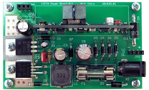
Let us now go through different parts which make a power supply unit.
Parts of a Power supply
A typical Power supply unit consists of the following.
Transformer − An input transformer for the stepping down of the 230v AC power supply.
Rectifier − A Rectifier circuit to convert the AC components present in the signal to DC components.
Smoothing − A filtering circuit to smoothen the variations present in the rectified output.
Regulator − A voltage regulator circuit in order to control the voltage to a desired output level.
Load − The load which uses the pure dc output from the regulated output.
Block Diagram of a Power Supply Unit
The block diagram of a Regulated Power supply unit is as shown below.
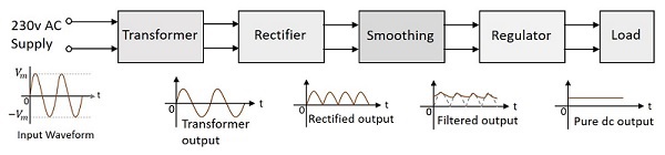
From the diagram above, it is evident that the transformer is present at the initial stage. Though we had already gone through the concept regarding transformers in BASIC ELECTRONICS tutorial, let us have a glance over it.
Transformer
A transformer has a primary coil to which input is given and a secondary coil from which the output is collected. Both of these coils are wound on a core material. Usually an insulator forms the Core of the transformer.
The following figure shows a practical transformer.
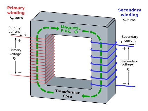
From the above figure, it is evident that a few notations are common. They are as follows −
$N_{p}$ = Number of turns in the primary winding
$N_{s}$ = Number of turns in the secondary winding
$I_{p}$ = Current flowing in the primary of the transformer
$I_{s}$ = Current flowing in the secondary of the transformer
$V_{p}$ = Voltage across the primary of the transformer
$V_{s}$ = Voltage across the secondary of the transformer
$\phi$ = Magnetic flux present around the core of the transformer
Transformer in a Circuit
The following figure shows how a transformer is represented in a circuit. The primary winding, the secondary winding and the core of the transformer are also represented in the following figure.
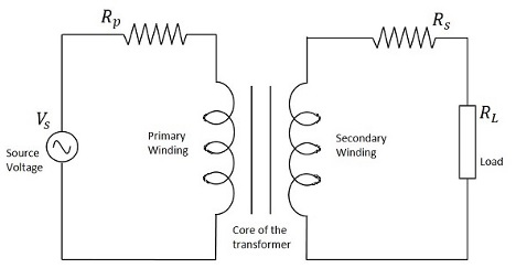
Hence, when a transformer is connected in a circuit, the input supply is given to the primary coil so that it produces varying magnetic flux with this power supply and that flux is induced into the secondary coil of the transformer, which produces the varying EMF of the varying flux. As the flux should be varying, for the transfer of EMF from primary to secondary, a transformer always works on alternating current AC.
Depending upon the number of turns in the secondary winding, a transformer can be classified either as a Step-up or a Step-down transformer.
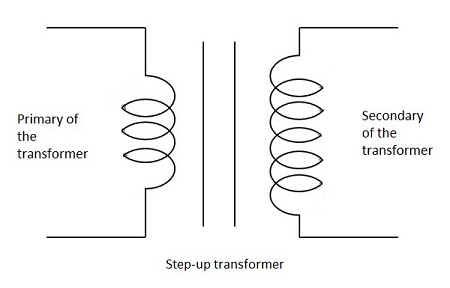
Step-Up Transformer
When the secondary winding has more number of turns than the primary winding, then the transformer is said to be a Step-up transformer. Here the induced EMF is greater than the input signal.
The figure below shows the symbol of a step-up transformer.
Step-Down Transformer
When the secondary winding has lesser number of turns than the primary winding, then the transformer is said to be a Step-down transformer. Here the induced EMF is lesser than the input signal.
The figure below shows the symbol of a step-down transformer.
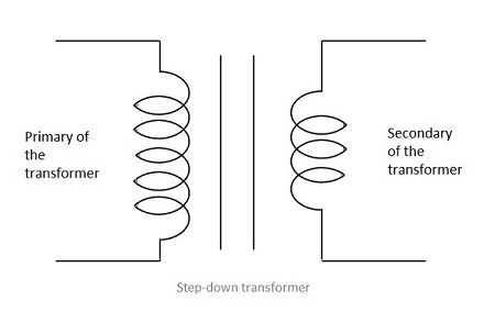
In our Power supply circuits, we use the Step-down transformer, as we need to lessen the AC power to DC. The output of this Step-down transformer will be less in power and this will be given as the input to the next section, called rectifier. We will discuss about rectifiers in the next chapter.