- UML - Home
- UML - Overview
- UML - Challenges & Real-world Applications
- UML - Building Blocks
- UML - Architecture
- UML - Modeling Types
- UML - Basic Notations
- UML - Standard Diagrams
- UML - Class Diagram
- UML - Object Diagram
- UML - Component Diagram
- UML - Deployment Diagram
- UML - Use Case Diagram
- UML - Interaction Diagram
- UML - Statechart Diagram
- UML - Activity Diagram
- UML - Communication Diagram
- UML - Timing Diagram
- UML - Sequence Diagram
- UML - Collaboration Diagrams
- UML - Profile Diagram
- UML - Sequence Vs. Collaboration Diagrams
- UML - Sequence Vs. Collaboration Vs. Communication Diagrams
- UML - Association Vs. Aggregation Vs. Composition
- UML - Interaction Overview Diagram
- UML - Composite Structure Diagram
- UML - Object Constraint Language
- UML - Managing Models
- UML - Summary
- UML Useful Resources
- UML - UML Interview Questions & Answers
- UML - Useful Resources
- UML - Knowledge Test
UML - Deployment Diagrams
Deployment diagrams are used to visualize the topology of the physical components of a system, where the software components are deployed.
Deployment diagrams are used to describe the static deployment view of a system. Deployment diagrams consist of nodes and their relationships.
Purpose of Deployment Diagrams
The term Deployment itself describes the purpose of the diagram. Deployment diagrams are used for describing the hardware components, where software components are deployed. Component diagrams and deployment diagrams are closely related.
Component diagrams are used to describe the components and deployment diagrams shows how they are deployed in hardware.
UML is mainly designed to focus on the software artifacts of a system. However, these two diagrams are special diagrams used to focus on software and hardware components.
Most of the UML diagrams are used to handle logical components but deployment diagrams are made to focus on the hardware topology of a system. Deployment diagrams are used by the system engineers.
The purpose of deployment diagrams can be described as −
Visualize the hardware topology of a system.
Describe the hardware components used to deploy software components.
Describe the runtime processing nodes.
How to Draw a Deployment Diagram?
Deployment diagram represents the deployment view of a system. It is related to the component diagram because the components are deployed using the deployment diagrams. A deployment diagram consists of nodes. Nodes are nothing but physical hardware used to deploy the application.
Deployment diagrams are useful for system engineers. An efficient deployment diagram is very important as it controls the following parameters −
Performance
Scalability
Maintainability
Portability
Before drawing a deployment diagram, the following artifacts should be identified −
Nodes
Relationships among nodes
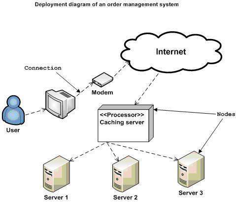
Following is a sample deployment diagram to provide an idea of the deployment view of order management system. Here, we have shown nodes as −
Monitor
Modem
Caching server
Server
The application is assumed to be a web-based application, which is deployed in a clustered environment using server 1, server 2, and server 3. The user connects to the application using the Internet. The control flows from the caching server to the clustered environment.
The following deployment diagram has been drawn considering all the points mentioned above.
Where to Use Deployment Diagrams?
Deployment diagrams are mainly used by system engineers. These diagrams are used to describe the physical components (hardware), their distribution, and association.
Deployment diagrams can be visualized as the hardware components/nodes on which the software components reside.
Software applications are developed to model complex business processes. Efficient software applications are not sufficient to meet the business requirements. Business requirements can be described as the need to support the increasing number of users, quick response time, etc.
To meet these types of requirements, hardware components should be designed efficiently and in a cost-effective way.
Now-a-days software applications are very complex in nature. Software applications can be standalone, web-based, distributed, mainframe-based and many more. Hence, it is very important to design the hardware components efficiently.
Deployment diagrams can be used −
To model the hardware topology of a system.
To model the embedded system.
To model the hardware details for a client/server system.
To model the hardware details of a distributed application.
For Forward and Reverse engineering.