- Radar Systems - Home
- Radar Systems - Overview
- Radar Systems - Range Equation
- Performance Factors
- Radar Systems - Types of Radars
- Radar Systems - Pulse Radar
- Radar Systems - Doppler Effect
- Radar Systems - CW Radar
- Radar Systems - FMCW Radar
- Radar Systems - MTI Radar
- Delay Line Cancellers
- Radar Systems - Tracking Radar
- Antenna Parameters
- Radar Systems - Radar Antennas
- Matched Filter Receiver
- Radar Systems - Radar Displays
- Radar Systems - Duplexers
- Phased Array Antennas
Radar Systems - Radar Antennas
In this chapter, let us learn about the Antennas, which are useful in Radar communication. We can classify the Radar Antennas into the following two types based on the physical structure.
- Parabolic Reflector Antennas
- Lens Antennas
In our subsequent sections, we will discuss the two types of Antennas in detail.
Parabolic Reflector Antennas
Parabolic Reflector Antennas are the Microwave Antennas. A knowledge of parabolic reflector is essential to understand about working of antennas in depth.
Principle of Operation
Parabola is nothing but the Locus of points, which move in such a way that its distance from the fixed point (called focus) plus its distance from a straight line (called directrix) is constant.
The following figure shows the geometry of parabolic reflector. The points F and V are the focus (feed is given) and the vertex respectively. The line joining F and V is the axis of symmetry. $P_1Q_1, P_2Q_2$ and $P_3Q_3$ are the reflected rays. The line L represents the directrix on which the reflected points lie (to say that they are being collinear).
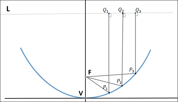
As shown in the figure, the distance between F and L lie constant with respect to the waves being focussed. The reflected wave forms a collimated wave front, out of the parabolic shape. The ratio of focal length to aperture size (i.e., $f/D$ ) is known as f over D ratio. It is an important parameter of parabolic reflector and its value varies from 0.25 to 0.50.
The law of reflection states that the angle of incidence and the angle of reflection are equal. This law when used along with a parabola helps the beam focus. The shape of the parabola when used for the purpose of reflection of waves, exhibits some properties of the parabola, which are helpful for building an Antenna, using the waves reflected.
Properties of Parabola
Following are the different properties of Parabola −
All the waves originating from focus reflect back to the parabolic axis. Hence, all the waves reaching the aperture are in phase.
As the waves are in phase, the beam of radiation along the parabolic axis will be strong and concentrated.
Following these points, the parabolic reflectors help in producing high directivity with narrower beam width.
Construction & Working of a Parabolic Reflector
If a Parabolic Reflector Antenna is used for transmitting a signal, the signal from the feed comes out of a dipole Antenna or horn Antenna, to focus the wave on to the parabola. It means that, the waves come out of the focal point and strike the paraboloid reflector. This wave now gets reflected as collimated wave front, as discussed previously, to get transmitted.
The same Antenna is used as a receiver. When the electromagnetic wave hits the shape of the parabola, the wave gets reflected onto the feed point. The dipole Antenna or the horn Antenna, which acts as the receiver Antenna at its feed receives this signal, to convert it into electric signal and forwards it to the receiver circuitry.
The gain of the paraboloid is a function of aperture ratio $D/\lambda$. The Effective Radiated Power (ERP) of an Antenna is the multiplication of the input power fed to the Antenna and its power gain.
Usually a wave guide horn Antenna is used as a feed radiator for the paraboloid reflector Antenna. Along with this technique, we have the following two types of feeds given to the paraboloid reflector Antenna.
- Cassegrain Feed
- Gregorian Feed
Cassegrain Feed
In this type, the feed is located at the vertex of the paraboloid, unlike in the parabolic reflector. A convex shaped reflector, which acts as a hyperboloid is placed opposite to the feed of the Antenna. It is also known as secondary hyperboloid reflector or sub-reflector. It is placed in such a way that one of its foci coincides with the focus of the paraboloid. Thus, the wave gets reflected twice.
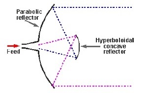
The above figure shows the working model of the cassegrain feed.
Gregorian Feed
The type of feed where a pair of certain configurations are there and where the feed beam width is progressively increased while Antenna dimensions are held fixed is known as Gregorian feed. Here, the convex shaped hyperboloid of Cassegrain is replaced with a concave shaped paraboloid reflector, which is of course, smaller in size.
These Gregorian feed type reflectors can be used in the following four ways −
Gregorian systems using reflector ellipsoidal sub-reflector at foci F1.
Gregorian systems using reflector ellipsoidal sub-reflector at foci F2.
Cassegrain systems using hyperboloid sub-reflector (convex).
Cassegrain systems using hyperboloid sub-reflector (concave but the feed being very near to it).
Among the different types of reflector Antennas, the simple parabolic reflectors and the Cassegrain feed parabolic reflectors are the most commonly used ones.
Lens Antennas
Lens Antennas use the curved surface for both transmission and reception of signals. These antennas are made up of glass, where the converging and diverging properties of lens are followed. The frequency range of usage of Lens Antenna starts at 1 GHz but its use is greater at 3 GHz and above.
A knowledge of Lens is required to understand the working of Lens Antenna in depth. Recall that a normal glass Lens works on the principle of refraction.
Construction & Working of Lens Antenna
If a light source is assumed to be present at a focal point of a lens, which is at a focal distance from the Lens, then the rays get through the Lens as collimated or parallel rays on the plane wave front.
There are two phenomena that happens when rays fall from different sides of a lens. They are given here −
The rays that pass through the centre of the Lens are less refracted than the rays that pass through the edges of the Lens. All of the rays are sent in parallel to the plane wave front. This phenomenon of Lens is called as Divergence.
The same procedure gets reversed if a light beam is sent from the right side to the left side of the same Lens. Then the beam gets refracted and meets at a point called the focal point, at a focal distance from the Lens. This phenomenon is called Convergence.
The following diagram will help us understand the phenomenon better.
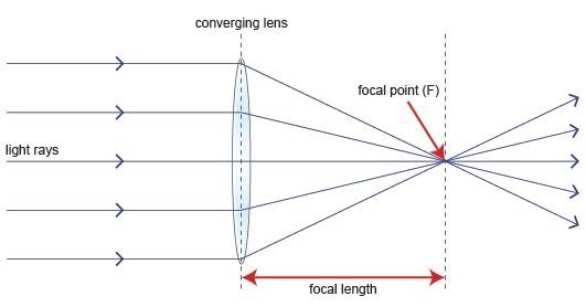
The ray diagram represents the focal point and the focal length from the source to the Lens. The parallel rays obtained are also called collimated rays.
In the above figure, the source at the focal point, at a focal distance from the Lens is collimated in the plane wave front. This phenomenon can be reversed which means the light if sent from the left side, is converged at the right side of the Lens.
It is because of this reciprocity, the Lens can be used as an Antenna, as the same phenomenon helps in utilizing the same Antenna for both transmission and reception.
To achieve the focusing properties at higher frequencies, the refractive index should be less than unity. Whatever may be the refractive index, the purpose of Lens is to straighten the waveform. Based on this, the E-plane and H-plane Lens are developed, which also delay or speed up the wavefront.