- Radar Systems - Home
- Radar Systems - Overview
- Radar Systems - Range Equation
- Performance Factors
- Radar Systems - Types of Radars
- Radar Systems - Pulse Radar
- Radar Systems - Doppler Effect
- Radar Systems - CW Radar
- Radar Systems - FMCW Radar
- Radar Systems - MTI Radar
- Delay Line Cancellers
- Radar Systems - Tracking Radar
- Antenna Parameters
- Radar Systems - Radar Antennas
- Matched Filter Receiver
- Radar Systems - Radar Displays
- Radar Systems - Duplexers
- Phased Array Antennas
Radar Systems - Matched Filter Receiver
If a filter produces an output in such a way that it maximizes the ratio of output peak power to mean noise power in its frequency response, then that filter is called Matched filter.
This is an important criterion, which is considered while designing any Radar receiver. In this chapter, let us discuss the frequency response function of Matched filter and impulse response of Matched filter.
Frequency Response Function of Matched Filter
The frequency response of the Matched filter will be proportional to the complex conjugate of the input signals spectrum. Mathematically, we can write the expression for frequency response function, $H\left (f\right )$ of the Matched filter as −
$$H\left (f\right )=G_aS^\ast\left (f\right )e^{-j2\pi ft_1}\:\:\:\:\:Equation\:1$$
Where,
$G_a$ is the maximum gain of the Matched filter
$S\left (f\right )$ is the Fourier transform of the input signal, $s\left (t\right )$
$S^\ast\left (f\right )$ is the complex conjugate of $S\left (f\right )$
$t_1$ is the time instant at which the signal observed to be maximum
In general, the value of $G_a$ is considered as one. We will get the following equation by substituting $G_a=1$ in Equation 1.
$$H\left (f\right )=S^\ast\left (f\right )e^{-j2\pi ft_1}\:\:\:\:\:Equation\:2$$
The frequency response function, $H\left (f\right )$ of the Matched filter is having the magnitude of $S^\ast\left (f\right )$ and phase angle of $e^{-j2\pi ft_1}$, which varies uniformly with frequency.
Impulse Response of Matched Filter
In time domain, we will get the output, $h(t)$ of Matched filter receiver by applying the inverse Fourier transform of the frequency response function, $H(f)$.
$$h\left (t\right )=\int_{-\infty }^{\infty }H\left (f\right )e^{-j2\pi ft_1}df\:\:\:\:\:Equation\:3$$
Substitute, Equation 1 in Equation 3.
$$h\left (t\right )=\int_{-\infty }^{\infty }\lbrace G_aS^\ast\left (f\right )e^{-j2\pi ft_1}\rbrace e^{j2\pi ft}df$$
$$\Rightarrow h\left (t\right )=\int_{-\infty }^{\infty }G_aS^\ast\left (f\right )e^{-j2\pi f\left (t_1-t\right )}df\:\:\:\:\:Equation\:4$$
We know the following relation.
$$S^\ast\left (f\right )=S\left (-f\right )\:\:\:\:\:Equation\:5$$
Substitute, Equation 5 in Equation 4.
$$h\left (t\right )=\int_{-\infty }^{\infty }G_aS(-f)e^{-j2\pi f\left (t_1-t\right )}df$$
$$\Rightarrow h\left (t\right )=\int_{-\infty }^{\infty }G_aS^\left (f\right )e^{j2\pi f\left (t_1-t\right )}df$$
$$\Rightarrow h\left (t\right )=G_as(t_1t)\:\:\:\:\:Equation\:6$$
In general, the value of $G_a$ is considered as one. We will get the following equation by substituting $G_a=1$ in Equation 6.
$$h(t)=s\left (t_1-t\right )$$
The above equation proves that the impulse response of Matched filter is the mirror image of the received signal about a time instant $t_1$. The following figures illustrate this concept.
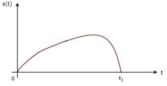
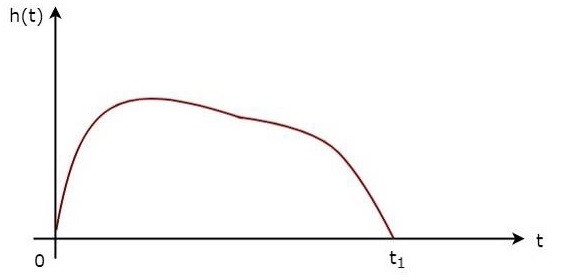
The received signal, $s\left (t\right )$ and the impulse response, $h\left (t\right )$ of the matched filter corresponding to the signal, $s\left (t\right )$ are shown in the above figures.