- Pulse Circuits Time Base Generators
- Time Base Generators (Overview)
- Types of Time Base Generators
- Bootstrap Time Base Generator
- Miller Sweep Generator
- Pulse Circuits Sweep Circuits
- Unijunction Transistor
- UJT as Relaxation Oscillator
- Pulse Circuits - Synchronization
- Pulse Circuits - Blocking Oscillators
- Pulse Circuits Sampling Gates
- Pulse Circuits - Sampling Gates
- Unidirectional Sampling Gate
- Unidirectional with More Inputs
- Bidirectional Sampling Gates
- Pulse Circuits Useful Resources
- Pulse Circuits - Quick Guide
- Pulse Circuits - Useful Resources
- Pulse Circuits - Discussion
Time Base Generators Overview
After having discussed the fundamentals of pulse circuits, let us now go through different circuits that generate and deal with Saw tooth waves. A Saw tooth wave increases linearly with time and has a sudden decrease. This is also called as a Time base signal. Actually, this is the ideal output of a time base generator.
What is a Time Base Generator?
An Electronic generator that generates the high frequency saw tooth waves can be termed as a Time Base Generator. It can also be understood as an electronic circuit which generates an output voltage or current waveform, a portion of which varies linearly with time. The horizontal velocity of a time base generator must be constant.
To display the variations of a signal with respect to time on an oscilloscope, a voltage that varies linearly with time, has to be applied to the deflection plates. This makes the signal to sweep the beam horizontally across the screen. Hence the voltage is called as Sweep Voltage. The Time Base Generators are called as Sweep Circuits.
Features of a Time Base Signal
To generate a time base waveform in a CRO or a picture tube, the deflecting voltage increases linearly with time. Generally, a time base generator is used where the beam deflects over the screen linearly and returns to its starting point. This occurs during the process of Scanning. A cathode ray tube and also a picture tube works on the same principle. The beam deflects over the screen from one side to the other (generally from left to right) and gets back to the same point.
This phenomenon is termed as Trace and Retrace. The deflection of beam over the screen from left to right is called as Trace, while the return of the beam from right to left is called as Retrace or Fly back. Usually this retrace is not visible. This process is done with the help of a saw tooth wave generator which sets the time period of the deflection with the help of RC components used.
Let us try to understand the parts of a saw-tooth wave.
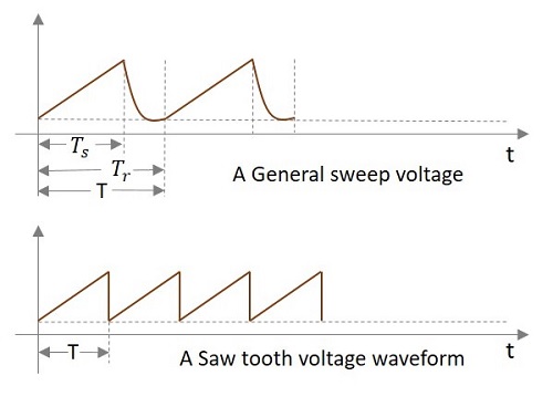
In the above signal, the time during which the output increases linearly is called as Sweep Time (TS) and the time taken for the signal to get back to its initial value is called as Restoration Time or Fly back Time or Retrace Time (Tr). Both of these time periods together form the Time period of one cycle of the Time base signal.
Actually, this Sweep voltage waveform we get is the practical output of a sweep circuit whereas the ideal output has to be the saw tooth waveform shown in the above figure.
Types of Time base Generators
There are two types of Time base Generators. They are −
Voltage Time Base Generators − A time base generator that provides an output voltage waveform that varies linearly with time is called as a Voltage Time base Generator.
Current Time Base Generator − A time base generator that provides an output current waveform that varies linearly with time is called as a Current Time base Generator.
Applications
Time Base Generators are used in CROs, televisions, RADAR displays, precise time measurement systems, and time modulation.
Errors of Sweep Signals
After generating the sweep signals, it is time to transmit them. The transmitted signal may be subjected to deviation from linearity. To understand and correct the errors occurred, we must have some knowledge on the common errors that occur.
The deviation from linearity is expressed in three different ways. They are −
- The Slope or Sweep Speed Error
- The Displacement Error
- The Transmission Error
Let us discuss these in detail.
The Slope or Sweep Speed Error (es)
A Sweep voltage must increase linearly with time. The rate of change of sweep voltage with time must be constant. This deviation from linearity is defined as Slope Speed Error or Sweep Speed Error.
Slope or Sweep speed eror es = $\frac{difference \: in\: slope\: at \: the\: beginning\: and\: end\: of\: sweep}{initial \: value \:of \: slope}$
$$= \frac{\left (\frac{\mathrm{d} V_0}{\mathrm{d} t} \right )_{t = 0} - \left( \frac{\mathrm{d} V_0}{\mathrm{d} t} \right)_{t = T_s}}{\left( \frac{\mathrm{d} V_0}{\mathrm{d} t}\right )_{t = 0}}$$
The Displacement Error (ed)
An important criterion of linearity is the maximum difference between the actual sweep voltage and the linear sweep which passes through the beginning and end points of the actual sweep.
This can be understood from the following figure.
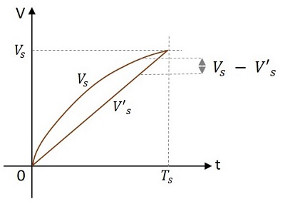
The displacement error ed is defined as
ed = $\frac{(actual\: speed)\thicksim (linear\: sweep \: that\: passes\: beginning \: and \: ending\: of\: actual\: sweep)}{amplitude\: of\: sweep\: at\: the \: end\: of\: sweep\: time}$
$$= \: \frac{(V_s - V_s)_{max}}{V_s}$$
Where Vs is the actual sweep and Vs is the linear sweep.
The Transmission Error (et)
When a sweep signal passes through a high pass circuit, the output gets deviated from the input as shown below.
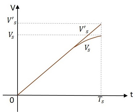
This deviation is expressed as transmission error.
Transmission Error = $\frac{(input)\: \thicksim \:(output)}{input\: at \: the\: end\: of\: the\: sweep}$
$$e_t = \frac{V_s V}{V_s}$$
Where Vs is the input and Vs is the output at the end of the sweep i.e. at t = Ts.
If the deviation from linearity is very small and the sweep voltage may be approximated by the sum of linear and quadratic terms in t, then the above three errors are related as
$$e_d = \frac{e_s}{8} = \frac{e_t}{4}$$
$$e_s = 2e_t = 8e_d$$
The sweep speed error is more dominant than the displacement error.