- MATLAB - Home
- MATLAB - Overview
- MATLAB - Features
- MATLAB - Environment Setup
- MATLAB - Editors
- MATLAB - Online
- MATLAB - Workspace
- MATLAB - Syntax
- MATLAB - Variables
- MATLAB - Commands
- MATLAB - Data Types
- MATLAB - Operators
- MATLAB - Dates and Time
- MATLAB - Numbers
- MATLAB - Random Numbers
- MATLAB - Strings and Characters
- MATLAB - Text Formatting
- MATLAB - Timetables
- MATLAB - M-Files
- MATLAB - Colon Notation
- MATLAB - Data Import
- MATLAB - Data Output
- MATLAB - Normalize Data
- MATLAB - Predefined Variables
- MATLAB - Decision Making
- MATLAB - Decisions
- MATLAB - If End Statement
- MATLAB - If Else Statement
- MATLAB - If…Elseif Else Statement
- MATLAB - Nest If Statememt
- MATLAB - Switch Statement
- MATLAB - Nested Switch
- MATLAB - Loops
- MATLAB - Loops
- MATLAB - For Loop
- MATLAB - While Loop
- MATLAB - Nested Loops
- MATLAB - Break Statement
- MATLAB - Continue Statement
- MATLAB - End Statement
- MATLAB - Arrays
- MATLAB - Arrays
- MATLAB - Vectors
- MATLAB - Transpose Operator
- MATLAB - Array Indexing
- MATLAB - Multi-Dimensional Array
- MATLAB - Compatible Arrays
- MATLAB - Categorical Arrays
- MATLAB - Cell Arrays
- MATLAB - Matrix
- MATLAB - Sparse Matrix
- MATLAB - Tables
- MATLAB - Structures
- MATLAB - Array Multiplication
- MATLAB - Array Division
- MATLAB - Array Functions
- MATLAB - Functions
- MATLAB - Functions
- MATLAB - Function Arguments
- MATLAB - Anonymous Functions
- MATLAB - Nested Functions
- MATLAB - Return Statement
- MATLAB - Void Function
- MATLAB - Local Functions
- MATLAB - Global Variables
- MATLAB - Function Handles
- MATLAB - Filter Function
- MATLAB - Factorial
- MATLAB - Private Functions
- MATLAB - Sub-functions
- MATLAB - Recursive Functions
- MATLAB - Function Precedence Order
- MATLAB - Map Function
- MATLAB - Mean Function
- MATLAB - End Function
- MATLAB - Error Handling
- MATLAB - Error Handling
- MATLAB - Try...Catch statement
- MATLAB - Debugging
- MATLAB - Plotting
- MATLAB - Plotting
- MATLAB - Plot Arrays
- MATLAB - Plot Vectors
- MATLAB - Bar Graph
- MATLAB - Histograms
- MATLAB - Graphics
- MATLAB - 2D Line Plot
- MATLAB - 3D Plots
- MATLAB - Formatting a Plot
- MATLAB - Logarithmic Axes Plots
- MATLAB - Plotting Error Bars
- MATLAB - Plot a 3D Contour
- MATLAB - Polar Plots
- MATLAB - Scatter Plots
- MATLAB - Plot Expression or Function
- MATLAB - Draw Rectangle
- MATLAB - Plot Spectrogram
- MATLAB - Plot Mesh Surface
- MATLAB - Plot Sine Wave
- MATLAB - Interpolation
- MATLAB - Interpolation
- MATLAB - Linear Interpolation
- MATLAB - 2D Array Interpolation
- MATLAB - 3D Array Interpolation
- MATLAB - Polynomials
- MATLAB - Polynomials
- MATLAB - Polynomial Addition
- MATLAB - Polynomial Multiplication
- MATLAB - Polynomial Division
- MATLAB - Derivatives of Polynomials
- MATLAB - Transformation
- MATLAB - Transforms
- MATLAB - Laplace Transform
- MATLAB - Laplacian Filter
- MATLAB - Laplacian of Gaussian Filter
- MATLAB - Inverse Fourier transform
- MATLAB - Fourier Transform
- MATLAB - Fast Fourier Transform
- MATLAB - 2-D Inverse Cosine Transform
- MATLAB - Add Legend to Axes
- MATLAB - Object Oriented
- MATLAB - Object Oriented Programming
- MATLAB - Classes and Object
- MATLAB - Functions Overloading
- MATLAB - Operator Overloading
- MATLAB - User-Defined Classes
- MATLAB - Copy Objects
- MATLAB - Algebra
- MATLAB - Linear Algebra
- MATLAB - Gauss Elimination
- MATLAB - Gauss-Jordan Elimination
- MATLAB - Reduced Row Echelon Form
- MATLAB - Eigenvalues and Eigenvectors
- MATLAB - Integration
- MATLAB - Integration
- MATLAB - Double Integral
- MATLAB - Trapezoidal Rule
- MATLAB - Simpson's Rule
- MATLAB - Miscellenous
- MATLAB - Calculus
- MATLAB - Differential
- MATLAB - Inverse of Matrix
- MATLAB - GNU Octave
- MATLAB - Simulink
MATLAB - Simulink
Simulink is a simulation and model-based design environment for dynamic and embedded systems, integrated with MATLAB. Simulink, also developed by MathWorks, is a data flow graphical programming language tool for modelling, simulating and analyzing multi-domain dynamic systems. It is basically a graphical block diagramming tool with customizable set of block libraries.
It allows you to incorporate MATLAB algorithms into models as well as export the simulation results into MATLAB for further analysis.
Simulink supports −
- system-level design
- simulation
- automatic code generation
- testing and verification of embedded systems
There are several other add-on products provided by MathWorks and third-party hardware and software products that are available for use with Simulink.
The following list gives brief description of some of them −
Stateflow allows developing state machines and flow charts.
Simulink Coder allows the generation of C source code for real-time implementation of systems automatically.
xPC Target together with x86-based real-time systems provide an environment to simulate and test Simulink and Stateflow models in real-time on the physical system.
Embedded Coder supports specific embedded targets.
HDL Coder allows to automatically generate synthesizable VHDL and Verilog.
SimEvents provides a library of graphical building blocks for modelling queuing systems.
Simulink is capable of systematic verification and validation of models through modelling style checking, requirements traceability and model coverage analysis.
Simulink Design Verifier allows you to identify design errors and to generate test case scenarios for model checking.
Using Simulink
To open Simulink, type in the MATLAB work space −
simulink
Simulink opens with the Library Browser. The Library Browser is used for building simulation models.
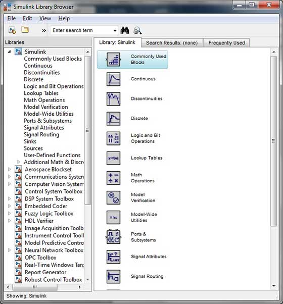
On the left side window pane, you will find several libraries categorized on the basis of various systems, clicking on each one will display the design blocks on the right window pane.
Building Models
To create a new model, click the New button on the Library Browser's toolbar. This opens a new untitled model window.
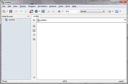
A Simulink model is a block diagram.
Model elements are added by selecting the appropriate elements from the Library Browser and dragging them into the Model window.
Alternately, you can copy the model elements and paste them into the model window.
Examples
Drag and drop items from the Simulink library to make your project.
For the purpose of this example, two blocks will be used for the simulation - A Source (a signal) and a Sink (a scope). A signal generator (the source) generates an analog signal, which will then be graphically visualized by the scope(the sink).
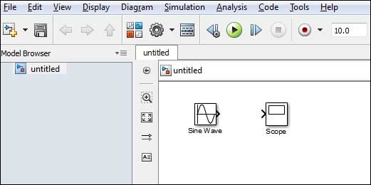
Begin by dragging the required blocks from the library to the project window. Then, connect the blocks together which can be done by dragging connectors from connection points on one block to those of another.
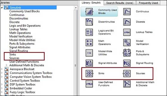
Let us drag a 'Sine Wave' block into the model.
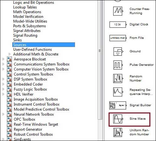
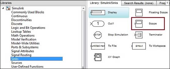
Select 'Sinks' from the library and drag a 'Scope' block into the model.
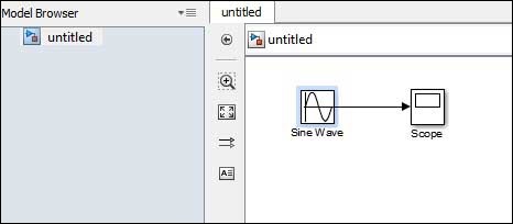
Drag a signal line from the output of the Sine Wave block to the input of the Scope block.
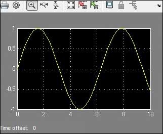
Run the simulation by pressing the 'Run' button, keeping all parameters default (you can change them from the Simulation menu)
You should get the below graph from the scope.