- Compiler Design - Home
- Compiler Design - Overview
- Compiler Design - Architecture
- Phases
- Compiler Design - Phases
- Compiler Design - Global Optimization
- Compiler Design - Local Optimization
- Lexical Analysis
- Compiler Design - Lexical Analysis
- Compiler Design - Regular Expressions
- Compiler Design - Finite Automata
- Compiler Design - Language Elements
- Compiler Design - Lexical Tokens
- Compiler Design - FSM
- Compiler Design - Lexical Table
- Compiler Design - Sequential Search
- Compiler Design - Binary Search Tree
- Compiler Design - Hash Table
- Syntax Analysis
- Compiler Design - Syntax Analysis
- Compiler Design - Parsing Types
- Compiler Design - Grammars
- Compiler Design - Classes Grammars
- Compiler Design - Pushdown Automata
- Compiler Design - Ambiguous Grammar
- Parsing
- Compiler Design - Top-Down Parser
- Compiler Design - Bottom-Up Parser
- Compiler Design - Simple Grammar
- Compiler Design - Quasi-Simple Grammar
- Compiler Design - LL(1) Grammar
- Error Recovery
- Compiler Design - Error Recovery
- Semantic Analysis
- Compiler Design - Semantic Analysis
- Compiler Design - Symbol Table
- Run Time
- Compiler Design - Run-time Environment
- Code Generation
- Compiler Design - Code Generation
- Converting Atoms to Instructions
- Compiler Design - Transfer of Control
- Compiler Design - Register Allocation
- Forward Transfer of Control
- Reverse Transfer of Control
- Code Optimization
- Compiler Design - Code Optimization
- Compiler Design - Intermediate Code
- Basic Blocks and DAGs
- Control Flow Graph
- Compiler Design - Peephole Optimization
- Implementing Translation Grammars
- Compiler Design - Attributed Grammars
Compiler Design - Control Flow Graph
Control Flow Graph
A Control Flow Graph visually represents the control flow of a program, illustrating how the program moves through different statements and decision points.
Frances E. Allen developed the control flow graph, drawing inspiration from Reese T. Prosser’s use of boolean connectivity matrices for flow analysis.
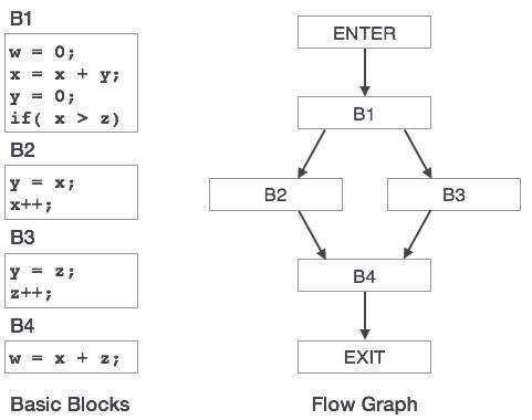
In a control-flow graph, each node corresponds to a basic block, which is a linear sequence of code that has only one entry point and one exit point, without any jumps or branches occurring inside the block. Basic blocks begin at jump targets and conclude with jumps or branch instructions. Directed edges are used to depict jumps in the control flow. Typically, two distinct blocks are identified: the entry block, where control first enters the flow graph, and the exit block, where all control flow exits.
How to Draw a Control Flow Graph?
Following are the simple rules that we can follow to draw a CFG.
- Each statement will be a node in the graph.
- Every node will have a directed edge either going to it or coming from it, or both.
- The entry node (first statement) will only have outgoing edges, and the exit node will only have incoming edges.
- Only conditional statements like if/else if, switch, and loops will have more than one outgoing edge.
- All paths from a node will converge at some point, with the worst case being convergence at the exit.
Example
The following are examples of control-flow graphs −
If then else − One path is taken when the condition is true (the "then" part), and another path is taken when the condition is false (the "else" part).

while loop − lets look at how a while loop is represented using a control flow graph. If it's true, it keeps doing the same set of actions (loop body). When the condition becomes false, the loop ends, and the next part of the program continues.

natural loop with two exits − while with an if...break in the middle; non-structured but reducible.

An irreducible CFG − a loop with two entry points, e.g. goto into a while or for loop.

Drawing a Control Flow Graph from Code
Let us draw a CFG for the given example to understand how the control flows through the program, combining related statements into basic blocks.
In this example, the if condition x > 5 isn't placed in its basic block. Instead, it's combined with the block before it because it always runs right after the print(x) call. This shows what is meant by treating basic blocks as maximal: while using a separate block for x > 5 is possible, doing so would be unnecessary.
x = 0
print(x)
if x > 5:
    print('x is big')
else:
    print('x is small')
Control Flow Graph
