Optical Networks - Quick Guide
Optical Networks - Introduction
The current thinking about IP over WDM by outlining a path to optical data networking, that includes multiple data networking protocol coupled with a protocol-neutral optical networking infrastructure is challenged. This tutorial discusses the diversity of data networking protocols and network architectures for optical data networking.
The bandwidth explosion ushered in by the popularity of the Internet has led to a paradigm shift in the telecommunication industry from voice-optimized circuit-switched services to data-optimized packet-switched services. The notation of supporting "data directly over optics" has been fueled by the promise that elimination of unnecessary network layers will lead to a vast reduction in the cost and complexity of the network.
In this view of reduced or collapsed network layers, existing TDM systems such as Synchronous Digital Hierarchy (SDH) plays a diminishing role, and optical transport networking emerges as the underlying transport infrastructure for the resultant "network of networks".
Optical Internet
Optical internet working, for example, as defined by the Optical Interworking Forum (OIF), is a data-optimized network infrastructure in which switches and routers have integrated optical interfaces and are directly connected by fiber or optical network elements, such as Dense Wavelength-Division Multiplexers (DWDMs).
At present, however, the notion of IP directly over WDM is little more than cleverly disguised marketing. Almost invariably, IP over WDM is IP packets mapped into SDH, coupled with SDH based point-to-point DWDM systems. SDH standalone elements, often referred to as Time-Division Multiplexer (TDMs), are not required, but SDH remains an integral element of the data networking equipment interface.
Ever-increasing reliance on the presence of SDH in DWDM systems limits technological innovation. For example, it may inhibit packet over fiber applications such as Asynchronous Transfer Mode (ATM), Gigabit Ethernet (GbE) and 10 GbE over DWDM. Nor does it bring us any closer to realizing the ultimate vision of optical transport networking.
As compared to the present view of IP over WDM, there is a more balanced view of data/transport network evolution. This balanced view is based on two fundamental principles −
Every data network is unique, in a marketplace governed by differentiation.
The Optical Transport Network (OTN), as the underlying infrastructure "network of networks" should be capable of transporting a wide variety of client signals, independent of their format.
Together, these fundamental principles form the basis for the notion of optical data networking.
Convergence Networks
Today's TDM-based transport networks have been designed to provide an assured level of performance and reliability for the predominant voice and based-line services. Proven technologies, such as SDH, have been widely deployed, providing high-capacity transport, scalable to gigabit per second rates, for voice and leased-line applications. SDH self- healing rings enable service-level recovery within tens of milliseconds following network failures. All of these features are supported by well- established global standards enabling a high degree of multivendor interoperability.
Todays Network
In contrast to today's TDM-based transport networks (and, to some extent, with ATM networks), "best-effort" IP networks generally lack the means to guarantee high reliability and predictable performance. The best-effort service provided by most legacy IP networks, with unpredictable delay, jitter, and packet loss, is the price paid to achieve maximum link utilization through statistical multiplexing. Link utilization (e.g. the number of users per unit of bandwidth) has been an important figure of merit for data networks, since the links are usually carried on leased circuits through the TDM transport network.
Given the inherently bursty nature of data traffic, the fixed-bandwidth pipes of TDM transport may not be an ideally efficient solution. However, this inefficiency has traditionally been considered of less importance important than the network reliability and congestion isolation features of a TDM-based transport network provider.
The surging demand for high bandwidth and differentiated data services is now challenging this dual architecture model of TDM-based transport and best effort packet networks. It is not cost- effective to extend the usefulness of best-effort networking by over provisioning network bandwidth and keeping the network lightly loaded.
Furthermore, this approach cannot always be achieved or guaranteed due to spotty demand growth, and is a particular issue for the network access domain, which is most sensitive to the economic constraints of underutilized facilities. As a result, in general, data service providers today do not have the network infrastructure support to provide customer- specific differentiated service guarantees and corresponding service-level agreements.
Next Generation Network
Next generation network architectures for cost-effective, reliable, and scalable evolution will employ both transport networking and enhanced service layers, working together in a complementary and interoperable fashion. These next-generation networks will dramatically increase, and maximally share, backbone network infrastructure capacity, and provide sophisticated service differentiation for emerging data applications.
Transport networking enables the service layers to operate more effectively, freeing them from constraints of physical topology to focus on the sufficiently large challenge of meeting service requirements. Hence, complementing the many service-layer enhancements, optical transport networking will provide a unified, optimized layer of high-capacity, high reliability bandwidth management, and create so-called optical data networking solutions for higher capacity data services with guaranteed quality.
Optical Transport Networking : A Practical View
Visions of optical networking have captured the imagination of researchers and network planners alike, since the rapid and successful commercialization of WDM. In the original vision of optical transport networking, a flexible, scalable, and robust transport network emerges, catering to an expanding variety of client signals with equally varied service requirements (flexibility, scalability, and survivability coupled with bit rate and protocol independence).
The promise of a transport infrastructure capable of meeting the burgeoning bandwidth demands well into this new century, wherein wavelengths replace timeslots as the medium for providing reliable transfer of high-bandwidth services across the network, is indeed tantalizing. But what is optical networking ? The answer varies widely, and in fact has evolved over recent years. Early attempts at optical networking focussed on an optical transparency and the design of optically transparent networks on a global scale.
Practical Solution
In the absence of viable "all-optical" solutions more practical solutions for optical networking accommodate the need for opto-electronics to support optical signal regeneration, and optical signal performance monitoring. In what is termed all-optical networking, signals traverse the network entirely in the optical domain, with no form of opto-electronic processing. This implies that the all signal processing- including - signal regeneration, routing, and wavelength interchange - takes place entirely in the optical domain.
Due to limitations of analog engineering (e.g. limiting factor in a properly designed digital system is an one accuracy of the conversion of the original analog message waveform into digital form) and considering the current state- of- the- art in all-optical processing technology, the notion of global or even national all optical networks is not practically attainable.
In particular, opto-electronic conversion may be required in opto network elements to prevent the accumulation of transmission impairments - impairments that result from such factors areas fiber fibre chromatic dispersion and nonlinearities, cascading of non-ideal flat-gain amplifiers, optical signal crosstalk, and transmission spectrum narrowing from cascaded non-flat filters. Opto-electronic conversion can also support wavelength interchange, which is currently a challenging feature to realize in to the all optical domain.
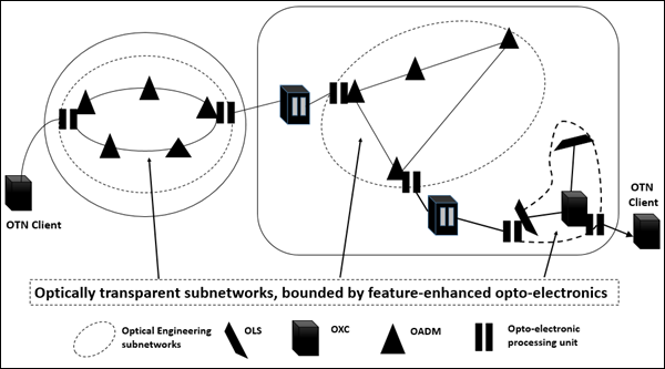
In short, in the absence of commercially available devices that perform signal regeneration to mitigate impairment accumulation and support wavelength conversion in the all-optical domain, some measure of opto-electronic conversion should be expected in near-term practical optical networking architectures. The resulting optical network architectures can be characterized by optically transparent (or all-optical) subnetworks, bounded by feature-enhanced opto-electronics, as shown in the above figure.
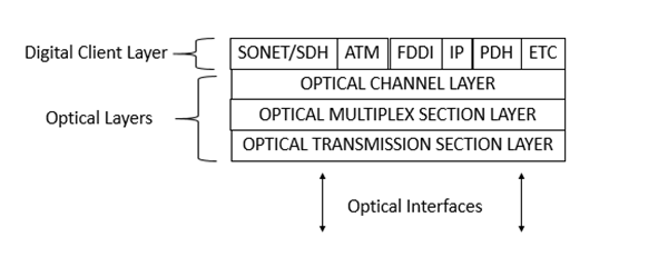
Client Signal Transparency
Beyond analog network engineering, practical considerations will continue to govern the ultimate realization of the OTN. Paramount among these considerations is the network operator's desire for a high degree of client signal transparency within the future transport infrastructure.
What is meant by "Client signal transparency"? Specifically, for the desired set of client signals targeted for transport on the OTN, individual mappings are defined for carrying these signals as payloads of optical channel (OCh) server signals. Signals expected in the OTN include legacy SDH and PDH signals, and packet-based traffic such as Internet Protocol (IP), ATM, GbE and Ssimple Ddata Llink (SDL). Once a client signal has been mapped into its OCh server signal at the ingress of the OTN, an operator deploying such a network need not have detailed knowledge of (or access to) the client signal, until it is demapped at the network egress.
The optical network ingress and egress points should delimit the domain of OTN client signal transparency. Hence, the most important factor in realizing client signal transparency is to eliminate all client-specific equipment and processing between OTN ingress and egress points. Fortunately, it is easier to accept client-dependent equipment at the ingress/egress, since it is generally dedicated on a per-service basis.
Optical Transport Networking via Digital Wrappers
The widespread use of DWDM technology has presented service providers with a new challenge : how to cost- effectively manage the increasing number of wavelengths to provide fast, reliable services to their end customers. To effectively manage wavelength or OChs, requires that optical networks support per wavelength or OCh-level operations, administration and maintenance (OAM) functions.
ITU(T) Rec. G872 defines some functionality for OCh-level OAM implemented in the form of overheads without specifying how this overhead is to be carried. Until now, the only feasible way to support signal regeneration and to monitor, analyze, and manage OChs (wavelengths) was to rely on SDH signals and equipment throughout the network. This requires that the signals on each of the wavelengths in the WDM system be SDH formatted.
An Optical Channel (Wavelength)
Taking advantage of the existing opto-electronic regeneration points in DWDM systems, the notion of using digital wrapper technology will provide functionality and reliability similar to SDH, but for any client signal, bringing us one step closer to realizing the original vision of optical transport networking.
Digital wrapper technology provides the network management functions outlined in ITU(T) Rec. G.872 to enable OTNs. These include optical-layer performance monitoring, Fforward Eerror Ccorrection (FEC), and ring protection and network restoration on a per-wavelength basis, all independent of the input signal format as is shown in the following figure.
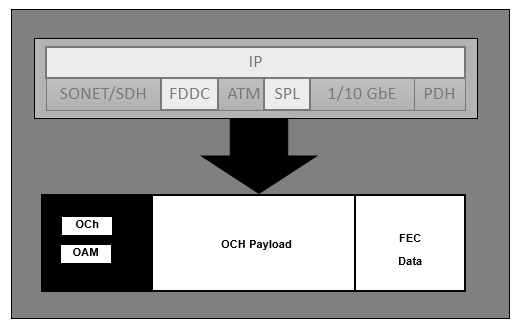
The notion of using a digital (or TDM) wrapper per "around" the OCh client to support channel-associated OCh overhead has recently been proposed, and has in fact, been adopted as the basis for definition of the OCh. This scheme will take advantage of the need for OCh regeneration to add additional capacity to the OCh client. Of course, once we have a means of adding overhead to the OCh client signal digitally, it makes sense to use this to support all of the OCh-level OAM requirements.
In particular, digitally added overhead makes it almost trivial to solve the major performance monitoring problem of the OTN, namely providing access to Bbit Eerror Rrate (BER) in a client-independent manner. BAnd by optionally using FEC, the digital wrapper method can significantly enhance the BER performance of the client signal, further minimizing the requirement for opto-electronic conversion.
One method of enhancing the performance of the transport network is through the use of FEC, which is currently provided in some equipment. Hence, an added benefit of the digital wrapper technique is the ability to optionally support FEC for system margin enhancement.
OCh Frame Structure
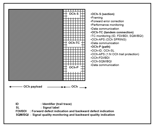
In functional terms, the OCh payload and OAM should be separable from the FEC mechanism. This allows for carrying the payload and OAM end to end across the network, while using different FEC schemes on different links. An obvious example of where this might occur is between submarine and terrestrial links. In the former, new FEC codes are under investigation for the next generation of systems.
Following figure Below Fig. illustrates the proposed basic frame structure of the OCh, and the types of functions that may be carried in the OCh frame structure. While it might be argued that this proposal is inconsistent with long-term goals of the all optical networking, we should not expect the need for regeneration to disappear.
The distance between regeneration points will continue to increase; however, the need for regeneration at signal handoff points will remain. Coupled with the use of the Ooptical Ssupervisory Cchannel (OSC) to manage OChs within optically transparent subnetworks, digital wrappers will support end- to- end management of OChs (wavelength) across national or global OTNs.
3R-regeneration (Reshaping, Retiming, and Regeneration) is provided by means of optical-to-electrical conversion and vice versa, and the digital wrapper proposal takes advantage of this. Would the picture change should all-optical 3R-regeneration becomes available? If all-optical regeneration is capable of adding overhead, the argument is unchanged; only the regenerator implementation would change.
If Should optical regenerators are be unable to add overhead, the need for OChs overhead will not disappear. ; Optical regenerators would then simply increase the potential distance between the opto-electronic regeneration points, and the digital wrapper would pass transparently through them. The implications of the use of digital wrappers on the evolution of optical transport networking may be profound, especially when taken in the context of data networking trends.
Protocol Stack Choices
The IP protocol is clearly the convergence layer in today's data communication networks, and it is foreseeable that it will expand this role to multi- service networks in the years to come. IP can be transported over a broad variety of data link layer protocols and underlying networking infrastructures. Following figure Below Fig. shows some of the possible protocol stacks, or mappings, of IP into a WDM network infrastructure.
What is IP over WDM ?
The protocol stacks labelled a, b and d in the following abovfiguree Fig. are the most commonly deployed today. They use the classical IP over ATM over SDH mapping as shown in Fig (a);. packet over SDH (POS) as shown in Fig. (b); or the classical and well-extended IP over Ethernet as shown in Fig. (d). Cases (e) and (f) use Simple Data Link (SDL), a new data link layer recently proposed as an alternative to POS. The protocol stack labeled (c) is an alternative to case (a), where the intermediate SDH layer is eliminated and a direct mapping of ATM cells into WDM is performed.

These different protocol stacks provide different functionality, in terms of bandwidth overhead, rate scalability, traffic management, and QOS. To state that any one particular mapping represents IP over WDM is extremely disingenuous.
This diversity of data link layer protocols and mappings of IP into different underlying network infrastructures is one of the major strengths of IP, and it is a characteristic that will not disappear. On the contrary, it is quite very possible that new, innovative, and more efficient protocol mapping will be proposed for the transport of IP packets. This is already the case for low-bandwidth and low-reliability networks, and will also be so for high-bandwidth and highly-reliable optical networks. This view also fits within the vision of "everything on IP and IP on everything".
Optical Data Networking
IP over WDM, as defined today, imposes a restrictive view of the capabilities that data networks and optical networks can provide. The constraints, introduced by a single protocol stack and not by fully using the networking capabilities at the optical layer are very restrictive for some network applications.
The networking trends mentioned above require an optical networking platform that can support a variety of protocol stacks, network architectures, and protection and restoration options in a client-signal independent way. The POS over point-to-point WDM choice is best for some of the network applications in high-speed data networks, but certainly not for all. Also, the optical platform selected to implement and deploy these future data networks must ensure that new, unexpected protocol stack mappings can easily be accommodated, and they can receive the same networking features from the optical layer network without the need for an intermediate protocol conversion.
Optical data networking is an alternative approach that does not try to reduce the heterogeneity of protocol stacks and network architectures, but rather exploits the heterogeneity to provide tailored network solutions to each particular application and network provider segment. Optical data networking combines networking features at both the service and transport layers.
Main Component of Optical Data Networking
The diversity of protocol stacks, reflected in the multiplicity of client signal types to be supported in the OTN, is accommodated by the use of digital wrappers. The use of true optical networking features offer additional flexibility and robustness via OCh routing, fault and performance monitoring, protection, and restoration, all performed on a selective per OCh basis. All these elements combined together render a powerful and flexible networking solution that is future-proof and open to any particular vision of data service providers.
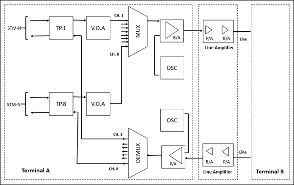
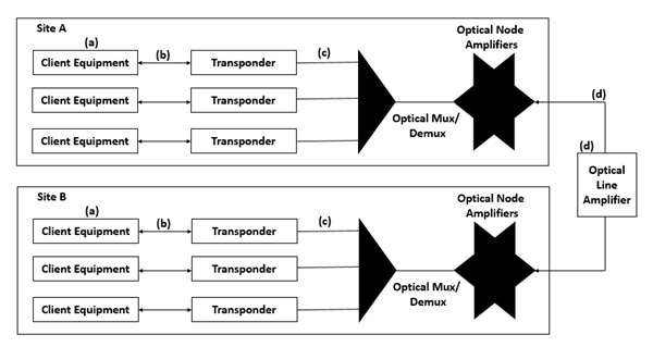
This technology is cost-effective and more flexible for the upgradation of channel capacity, adding/dropping of channels, re-routing and traffic distribution, supporting all types of network topology and protection systems and synchronization. Following are the main components −
- TP (Transponder)
- VOA (Variable Optical Attenuator)
- MUX (Multiplexer)
- DEMUX (De-multiplexer)
- BA (Booster Amplifier)
- Line (OFC media)
- LA (Line Amplifier)
- PA (Pre Amplifier)
- OSC (Optical Supervisory Channel)
Transponder
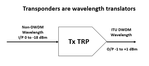
This unit is an interface between STM-n wide pulse optical signal and MUX/DEMUX equipments. This optical signal may be co-located or coming from different physical mediums, different protocols, and traffic types. It converts the wide pulse signal into a narrow wavelength (spot or colored frequency) of the order of nano-meter (nm) with spacing of 1.6 nm; sending to MUX.
In the reverse direction, colored output from the DEMUX is converted to a wide pulse optical signal. The output power level is +1 to 3 dBm in both directions. The conversion is Optical to Electrical and Electrical to Optical (O to E & E to O) in 2R or 3R method.
In 2R, regeneration and re-shaping are done, while in 3R, regeneration, re-shaping, and re-timing are performed. TP may be the wavelength color and bit rate dependent or tunable for both (costly and not used). However, in 2R, any bit rate, PDH, STM-4 or STM-16 may be the channel rate. The unit has a limitation with the receiver sensitivity and overload point.
Though the intermediate electrical stage is inaccessible, overhead bytes of STN-n are utilized for supervisory purpose. This unit also supports optical safety operation (ALS) over ITU-T Recommendation G.957.
Variable Optical Attenuator (VOA)
This is a passive network like pre-emphasis required to adjust for uniform distribution of signal level over EDFA band so that individual channel optical output power of Mux unit remains the same irrespective of the number of channels being loaded in the system.
The optical attenuator is similar to a simple potentiometer or circuit used to reduce a signal level. The attenuator is used whenever performance test must be run, for example, to see how the bit error is affected by varying the signal level in the link. One way is to have a precise mechanical setup in which the optical signal passes through a glass plate with differing amount of darkness and then back to the optical fiber, as shown in the figure.
The glass plate has grey density ranging from 0% at one end to 100% at the other end. As the plate is moved across the gap, more or less light energy is allowed to pass. This type of attenuator is very precise, and can handle any light wavelength (since the plate attenuates any light energy by the same amount, regardless of the wavelength), but it is mechanically expensive.
Multiplexer (MUX) and Demultiplexer (De-MUX)
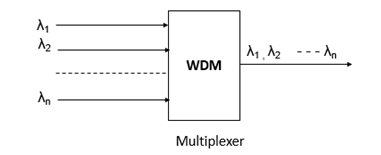
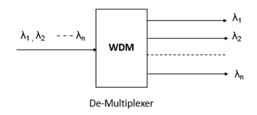
As DWDM systems send signals from several stations over a single fiber, they must include some means to combine the incoming signals. This is done with the help of a Multiplexer, which takes optical wavelengths from multiple fibers and converges them into a beam. At the receiving end, the system must be able to separate out the transmitted wavelengths of the light beam so that they can be discreetly detected.
Demultiplexers perform this function by separating the received beam into its wavelength components and coupling them into individual fibers.
Multiplexers and Demultiplexers can be either passive or active in design. Passive design uses prism, diffraction gratings, or filters while active design combines passive devices with tunable filters.
The primary challenges in these devices are to minimize crosstalk and maximize channel separation (the wavelength difference between two adjacent channels). Crosstalk is a measure of how well the channels are separated, while channel separation refers to the ability to distinguish each wavelength.
Types of Multiplexer/ Demultiplexer
Prism Type
A simple form of multiplexing or demultiplexing of wavelengths can be done using a prism.
A parallel beam of polychromatic light impinges on a prism surface and each component wavelength is refracted differently. This is the rainbow effect. In the output light, each wavelength is separated from the next by an angle. A lens then focuses each wavelength to the point where it needs to enter a fiber. The components can be used in reverse to multiplex different wavelengths on to one fiber.
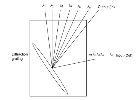
Diffraction Grating Type
Another technology is based on the principle of diffraction and of optical interference. When a polychromatic light source impinges on diffraction grating, each wavelength is diffracted at a different angle and therefore to a different point in space. Using a lens, these wavelengths can be focused on to individual fibers, as shown in the following figure. Bragg grating, is a simple passive component, which can be used as wavelength selective mirrors and are widely used to add and drop channels in DWDM systems.
Braggs grating are made by using an ultra-violet laser beam to illuminate the core of a mono mode fiber through a phase mask. The fiber is doped with phosphorus, germanium, or boron to make it photo sensitive. After the light has passed through the mask, a fringe pattern is produced, which is printed into the fiber. This creates a permanent periodic modulation of the refractive index of the fiber core glass. The finished grating reflects light at the Bragg wavelength (equal to twice the optical spacing between the high and the low index regions) and transmits all other wavelengths.
Tunable Bragg Grating
A Bragg fiber grating can be glued to a piezoelectric element. By applying a voltage to the element, the element stretches so that grating is stretched and the Bragg wavelength shifts to a longer wavelength. Present devices can provide a tuning range of 2 nm for an input of 150v.
Arrayed Waveguide Grating
Arrayed Waveguide Gratings (AWG) are also based on diffraction principles. An AWG device, sometimes called an optical waveguide router or waveguide grating router, consists of an array of curved channel waveguide with a fixed difference in the path length between adjacent channels. The waveguides are connected to cavities at the input and output.
Optical Multiplexer
When the light enters the input cavity, it is diffracted and enters the wave-guide array. Thus the optical length difference of each wave guide introduces phase delays in the output cavity, where an array of fibers is coupled. The process results in different wavelengths having maximum interference at different location, which corresponds to the output ports.
Multilayer Interference Filters
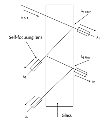
A different technology uses interference filters in devices called thin film filters or multilayer interference filters. By positioning the filters, consisting of thin films in the optical path, wavelength can be demultiplexed. The property of each filter is such that it transmits one wavelength, while reflecting others. By cascading these devices, many wavelengths can be demultiplexed.
Filters offer good stability and isolation between channels at moderate cost, but with a high insertion loss (AWGs exhibit a flat spectral response and low insertion loss). The main drawback of the filter is that they are temperature sensitive and may not be practically used in all environments. However, their big advantage is that they can be designed to perform multiplexing and demultiplexing operations simultaneously.
Coupling Type of the OM
The coupling OM is a surface interactive with two or more fibers soldered together. Generally, it is used for the OM, and its working principles are illustrated in the following figure.
The coupling OM can only perform multiplexing function with low manufacture cost. Its shortcoming is high insertion loss. Presently, the OM used in the DWDM equipment of ZTWE employs the coupling OM. The OD adopts the AWG components.
Booster Amplifiers (Optical Amplifiers)
Due to attenuation, there are limits to how long a fiber segment can propagate a signal with integrity, before it has to be regenerated. Before the arrival of Optical Amplifiers (OAs), there had to be a repeater for every signal transmitted. The OA had made it possible to amplify all the wavelengths at once and without Optical-Electrical-Optical (OEO) conversion. Besides being used in optical links (as repeater), optical amplifiers can also be used to boost signal power after multiplexing or before demultiplexing.
Types of Optical Amplifiers
In every optical route, the optical amplifiers were used as repeaters in a simplex mode. One fiber was used in send path and the second fiber was used in return path. The latest optical amplifiers will operate in two directions at the same time. We can even use the same wavelength in two directions, provided two different bit rates are employed. A single fiber can, therefore, be used for duplex operation.
The optical amplifiers must also have sufficient bandwidth to pass a range of signals operating at different wavelengths. For example, an SLA with a spectral bandwidth of say, 40 nm, can handle about ten optical signals.
In 565 mb/s system, for 500 kms optical link, five SLA optical amplifiers are required, spaced at an interval of 83 kms. Each amplifier provides a gain of about 12 dB, but also introduces noise to the system (BER of 10-9.)
SLA amplifiers have the following disadvantages −
- Sensitive to temperature changes
- Sensitive to supply voltage changes
- Sensitive to mechanical vibrations
- Unreliable
- Prone to crosstalk
Erbium Doped Fiber Amplifier (EDFA)
In DWDM systems, EDFAs are used. Erbium is a rare earth element that, when excited, emits light around 1.54 micrometers, which is the low loss wavelength for optical fibers used in DWDM. A weak signal enters the erbium-doped fiber, into which light at 980 nm or 1480 nm is injected using a pump laser.
This injected light stimulates the erbium atoms to release their stored energy as additional 1550 nm light. The signal grows strong. The spontaneous emissions in the EDFAs also add noise figure of an EDFA. EDFAs have a typical bandwidth of 100 nm and are needed at an interval of 80-120 kms along the optical route.
EDFA also suffer from an affect called four-wave-mixing due to non-linear interaction between the adjacent channels. Hence, increasing the amplifier power to increase the distance between the repeaters leads to more crosstalk.
Raman Amplifier
The use of SLA and EDFA amplifiers in WDM is limited as already described and, the modern WDM systems are turning to Raman Amplification, which has a bandwidth of about 300 nm. Here, the pump laser is at the receiving end of the fiber. Crosstalk and noise are greatly reduced. However, Raman amplification requires a high pump laser to be used.
Dispersion in the fiber actually helps to minimize the four wave mixing effect. Unfortunately, early optical links often used zero-dispersion fiber in an effort to minimize dispersion over long distances, when these same fibers are upgraded to carry WDM signals; they are not the ideal medium for wideband optical signals.
Special mono mode fibers are being developed for WDM use. These have alternate segments of positive and negative dispersion fibers, hence, the total dispersion adds up to zero. The individual segments, however, provide dispersion to prevent four-wave mixing.
Line Amplifiers
It is a two-stage EDFA amplifier consisting of Pre-amplifier (PA) and Booster Amplifier (BA). Without the two stages, it is not possible to amplify the signal up to 33 dB on EDFA principle (to avoid the noise generated by spontaneous emission). Line Amplifier (LA) compensates the line loss of 22 dB or 33 dB for long and very long haul systems respectively. It is entirely an optical stage device.
Line (OFC) Media
This is the optical fiber media over which the DWDM signals travel. Attenuation and dispersion are the main limitation factors determining the transmission distance, bit-rate capacity, etc. Normally, 22dB and 33dB are taken as line loss for hop length of long haul and very long haul systems, respectively.
The very long haul line wavelength can be 120 kms without repeater (LA). However, with a number of repeaters cascaded, the length may be up to 600 kms, which can further be, increased up to 1200 kms using the dispersion compensating module. After such a distance, it needs re-generation in electrical stage instead of the repeater in only the optical stage.
Pre-Amplifier (PA)
This amplifier alone is used at the terminal to interface the DEMUX and line for receiving the signal coming from the distant station. Hence, the attenuated line signal is amplified to a level of +3 dBm to 10 dBm before entering into DEMUX unit.
Optical Supervisory Channel
The function of transmission of additional data (2 mbps: EOW, user specific data etc via interface) at a separate wavelength (1480 nm as per ITU-T Recommendation G-692) of lower optical level without any optical safety provision, accompanied with and independent of the main STM-n optical traffic signal, is performed by the OSC. EOW (0.3 to 3.4 KHz) for selective and omnibus channel is 64 kbps in 8-bit PCM code.
The Optical Supervisory Channel (OSC) helps control and monitor the optical line devices as well as the management of fault location, configuration, performance and security accomplished using LCT.
Optical Networks - Devices
In this chapter, we will discuss the various components of optical devices.
Isolator
Isolator is a non-reciprocal device that allows light to pass along a fiber in one direction and offers very high attenuation in the opposite direction. Isolators are needed in the optical system to prevent unwanted reflections, coming back down a fiber and disrupting the operation of a laser (producing noise). In manufacturing isolators Faradays Effect is used, which is polarization dependent.
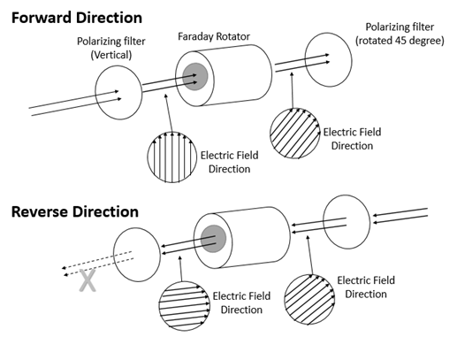
Isolators are constructed using optical polarizers, analyzers and Faradays rotator. The optical signal passes through the polarizer, oriented parallel to the incoming state of polarization. Faradays rotator will rotate the polarization of optical signal by 45 degrees.
The signal then passes through the analyzer, which is oriented at 45 degrees with respect to the input polarizer. The isolator passes an optical signal from left to right and changes its polarization by 45 degrees and produces about 2 dB loss.
Circulator
Circulators are micro-optic devices and can be used with any number of ports, however, commonly 3 ports/4 ports circulators are used. It has a relatively low loss 0.5 dB to 1.5 dB port-to-port.
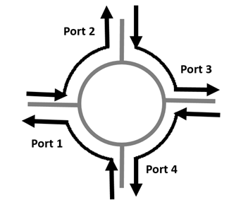
The basic function of a circulator is shown in the above figure. Light entering any particular port (say port 1) travels around the circulator and exits at the next port (say port 2). Light entering at port 2 leaves at port 3, and so on. The device is symmetric in operation around a circle. Circulators are micro-optic devices and can be made with any number of ports. However, 3 and 4 port circulators are very common. Circulators have very low loss. Typical port-to-port loss is around .5 to 1.5 db.
Splitters and Couplers
Couplers and splitters are used to combine optical signals and/or split the optical signals. The vast majority of single mode optical couplers employ the principle of resonant coupling. Two SM fiber cores are placed parallel and close to one another. Optical power transfers from one core to another and back by electromagnetic wave induction. Power coupling depends on the length of the coupling section.
Three important characteristics are −
Return Loss − The amount of power reflected and lost.
Insertion Loss − The amount of signal lost in total transit through a device.
Excess Loss − Additional loss of a device above theoretical loss.
Types of Couplers
- Y couplers
- Star couplers
- Fused fiber
- Mixing plate
- Planar (free space)
- 3 dB coupler
- Beam splitter
Filters
Filters are used to select the signal in trans path and receiver from many signals. The gratings are filters. Switches, modulators, AWGs, multiplexers, etc. are considered as types of filters.
Following are the types of filters −
- Fabry-Perot
- Tunable filter
- In-fiber Bragg grating filter
Filters are used in front of an LED to narrow the line width before transmission. Filters will be very useful in WDM networks for −
A filter placed in front of an incoherent receiver can be used to select a particular signal from many arriving signals.
WDM networks are proposed which use filters to control which path through a network a signal will take.
Fiber Bragg Gratings are the most important optical filter in the communications world.
Modulators
Modulators consist of a material that changes its optical properties under the influence of an electric or magnetic field. In general, three approaches are used −
- Electro-optic and Magneto-optic effects
- Electro-absorption effects
- Acoustic modulators
Due to mechanical vibrations Ref. Index of material changes. Acoustic modulators use very high frequency sound. By controlling the intensity of sound, we can control the amount of light deflected and hence, construct a modulator.
Following are some of its advantages −
They can handle quite high power.
Amount of light refracted is linearly proportional to the intensity of sound waves.
They can modulate different wavelengths at the same time.
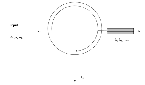
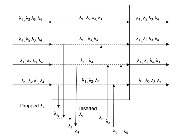
Optical ADM
An optical filter is used to isolate or drop the desired wavelength from multiple wavelengths arriving on a fiber. Once a wavelength is dropped, another channel employing the same wavelength can be added or inserted on to the fiber, as it leaves OADM.
A simple ADM has only 4 input and output channels, each with four wavelengths. In OADM, wavelengths might be amplified, equalized or further processed. OADM arranges the wavelengths from input fiber to output fiber using optical cross-connect.
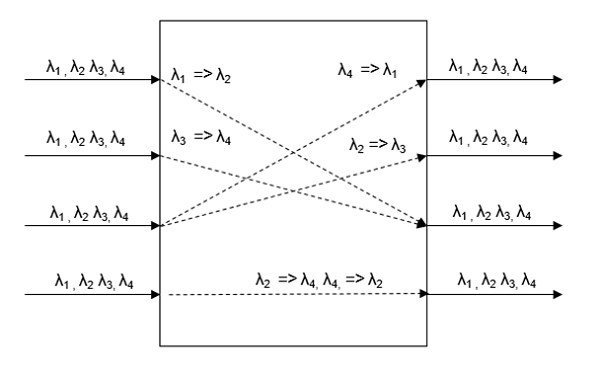
Optical Cross-Connect
An optical x-connect can take four input fibers, each carrying four wavelengths, and rearrange the 16 wavelengths, on to the four output fibers. A simple transponder inside OXC will shuffle one of the wavelengths to an available channel.
Single and Multi-hop Networks
Telecommunications traffic continues to grow at a very fast pace. This is accelerated through the increasing volume of data and mobile traffic, especially in India, through the recent liberalization of the telecommunications market. A solution can be adopted to meet the ever-increasing traffic requirements based on a combination of WDM, SDH, and IP transport technologies.
Wavelength-division multiplexing is used to multiplex several wavelength channels on a single strand of fiber, thus overcoming fiber congestion. SDH technology offers the capacity granularity, which the customers demand today and offers the possibility to protect these services against network outages. An IP-over-WDM transport network can offer high capacity Internet transit services to Internet Services Providers (ISPs).
Synchronous Digital Hierarchy
Synchronous Digital Hierarchy (SDH) networks replaced PDH and have several key advantages.
G.707, G.708, and G.709 ITU recommendations provide the basis for global networking.
Networks benefit from traffic resilience to minimize traffic loss in the event of fiber break or equipment failure.
Built-in monitoring technology allows remote configuration and troubleshooting of network.
Flexible technology allows tributary access at any level.
Future proof technology allows for faster bit rates as technology advances.
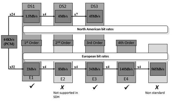
European PDH networks could not interface with US networks, SDH networks can carry both types. The above figure shows how the different PDH networks compare and which signals can be carried across the SDH network.
SDH - Network Topologies
A line system is the system to the PDH network topology. Traffic is added and dropped only at the endpoints of the network. Terminal nodes are used at the end of the network for adding and dropping the traffic.
Line System
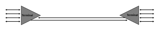
Within any SDH network, it is possible to use a node known as a regenerator. This node receives the high order SDH signal and retransmits it. No lower order traffic access is possible from a regenerator and they are only used to cover long distances between sites, where the distance means that the received power would be too low to carry traffic.
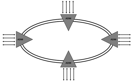
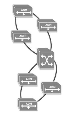
Ring System
A ring system consists of several add/drop muxes (ADMs) connected in a ring configuration. Traffic can be accessed at any ADM around the ring and it also possible for traffic to be dropped at several nodes for broadcast purposes. The ring network has the benefit of offering traffic resilience, if there is a fiber break traffic is not lost. Network resilience is discussed in detail in a subsequent chapter.
SDH Network Synchronization
While PDH networks were not centrally synchronized, SDH networks are (hence, the name synchronous digital hierarchy). Somewhere on the operators network will be a primary reference source. This source is distributed around the network either over the SDH network or over a separate synchronization network.
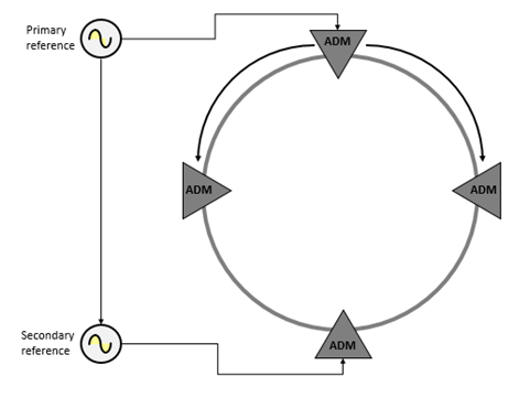
Each node can switch to backup sources, if the main source becomes unavailable. Various quality levels are defined and the node will switch the next best quality source it can find. In cases where the node uses the incoming line timing, the S1 byte in the MS overhead is used to denote the quality of the source.
The lowest quality source available to a node is generally its internal oscillator. In a case where a node switches to its own internal clock source, this should be remedied as soon as possible, as the node may start to generate errors over time.
It is important that the synchronization strategy for a network is planned carefully. If all the nodes in a network try to synchronize off its neighbor on the same side, you will get an effect called a timing loop, as shown in the above figure. This network will quickly start to generate errors as each node tries to synchronize off each other.
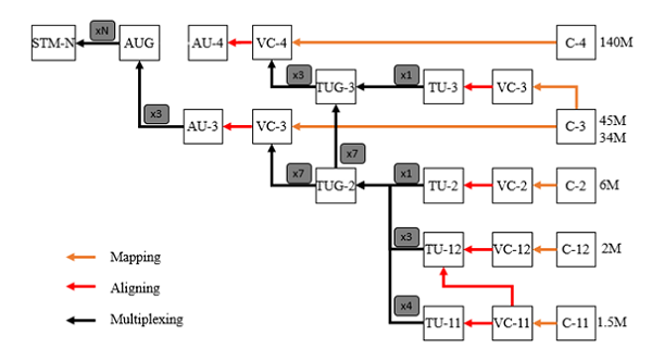
SDH Hierarchy
The following figure shows how the payload is constructed, and it isnt as scary as it looks at first.
Optical Networks - WDM Technology
WDM is a technology that enables various optical signals to be transmitted by a single fiber. Its principle is essentially the same as Frequency Division Multiplexing (FDM). That is, several signals are transmitted using different carriers, occupying non-overlapping parts of a frequency spectrum. In case of WDM, the spectrum band used is in the region of 1300 or 1550 nm, which are two wavelength windows at which optical fibers have very low signal loss.
Initially, each window was used to transmit a single digital signal. With the advance of optical components, such as Distributed Feedback (DFB) lasers, Erbium-doped Fiber Amplifiers (EDFAs), and photo-detectors, it was soon realized that each transmitting window could in fact be used by several optical signals, each occupying a small traction of the total wavelength window available.
In fact, the number of optical signals multiplexed within a window is limited only by the precision of these components. With the current technology, over 100 optical channels can be multiplexed into a single fiber. The technology was then named dense WDM (DWDM).
WDM in the Long Haul
In 1995, long-haul carriers in the United States started deploying point-to-point WDM transmission systems to upgrade the capacity of their networks while leveraging their existing fiber infrastructures. Since then, WDM has also taken the long-haul market by storm. WDM technology allows to cope with ever-increasing capacity requirements while postponing the exhaustion of fiber and increasing the flexibility for capacity upgrade.
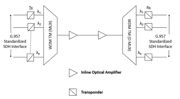
The most prevailing driver, however, is the cost advantage of the WDM solution compared to competing solutions, such as Space Division Multiplexing (SDM) or enhanced Time Division Multiplexing (TDM) to upgrade the network capacity. The "open" WDM solution, illustrated in the following figure makes use of transponders in WDM terminal multiplexers (TMs) and inline optical amplifiers that are shared by multiple wavelength channels.
The transponder is in essence a 3R opto-electro-optic (O/E/O) converter, that converts a G.957 standard compliant optical signal into an appropriate wavelength channel (and vice versa) while repowering, reshaping and retiming the signal electrically. The SDM solution uses multiple fiber pairs in parallel, each equipped with SDH regenerators instead of multiple wavelengths sharing the same inline optical amplifier. Upgrading to higher TDM rates (e.g., from 2.5 Gb/s STM-16 to 10 Gb/s STM-64) is only a short-lived solution since transmission impairments such as dispersion do not scale well with increasing TDM rates, especially on standard single-mode fiber.
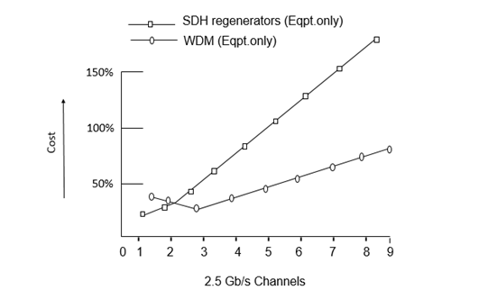
A case study has demonstrated that long haul point-to-point WDM systems are clearly a more cost-effective solution than SDM, even for as low as three channels of STM-16. The above figure illustrates two link cost comparisons for the initial core of a transport network consisting of 5000 fiber km with an average distance of 300 kms between two access cities. Note that the 100 percent cost reference point in the above figure corresponds to the cost of deploying one STM-16 channel, including fiber cost. Two conclusions can be derived from the above figure.
As shown in the following figure, if only transmission and regeneration equipment costs are considered (i.e., SDH regenerators in the SDM case and WDM TMs with transponders with inline optical amplifiers in the WDM case), the initial link cost of using WDM technology is more than double that of SDH. However, WDM solution is more cost-effective for the deployment of three channels and more in the network, because of the shared use of the inline optical amplifier.
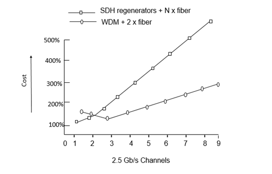
As shown in the following figure, if in addition to the above consideration, the fiber cost is also considered, the cost advantage of WDM case becomes even more evident and is amplified as the number of channels increase. WDM solution is more cost-effective for the deployment of three channels and more in the network.
WDM in the Short Haul
Regenerators are not necessary and optical impairments have less impact because of the limited distances in the short haul networks, hence the benefits of WDM are less clear than those of SDM or enhanced TDM solutions. However, fiber exhaustion and low-cost optical components are now driving WDM in the metropolitan area.
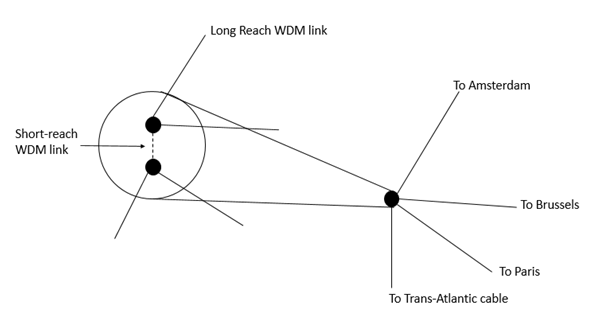
The short-haul application is related to the inter-connection of multiple Points of Presence (POPs) within the same city. Let us consider an example. The following figure shows that the transport network has at least two POPs per city, where the customers can interconnect. With dual node interconnection techniques, such as drop and continue, customer networks can be interconnected with the transport network via two different POPs.
This results in a very secure architecture that can even survive POP failures without any traffic impact. Thus, the traffic flow between two POPs in a city consists of not only traffic that passes through the city, but also of traffic that is terminated in the city and protected using Drop and Continue. These increased intra-city capacity requirements have led to the deployment of WDM in the short-haul section of a transport network.
The main reason WDM is preferred over SDM is because fibers in a city have to be leased from a third party or a fiber optic network has to be built. Leasing or building city fiber is not only an expensive process, it is also a less flexible approach to upgrade capacity. In a dynamic environment, where traffic distributions and volumes evolve rapidly, the amount of fiber to be leased or built is hard to predict in advance. Therefore, using WDM technology has clear flexibility advantages because the wavelength channels can be activated in a very short time.
Although specific short-haul WDM systems are available in the world, it is advantageous to use the same type of WDM system for its long-haul network. While short-haul WDM systems are less expensive than their long-haul counterparts and due to their low-cost optical components can be used, they lead to a heterogeneous network, which is not preferred for several reasons. First, using two different systems leads to an increased operational and management cost. For instance, a heterogeneous network requires more spare equipment parts than a homogeneous network. Second, the interworking between two different systems might pose problems. For instance, a bottleneck can occur because short-haul WDM systems typically support fewer wavelengths than long-haul WDM systems.
Optical Transport Network Architectures
Optical Transport Networking (OTN), as shown in the following figure, represents a natural next step in the evolution of transport networking. From a high-level architectural perspective, one would not expect OTN architectures to differ significantly from those of SDH. Nevertheless, the fact that SDH involves digital network engineering and OTN involves analog network engineering leads to some significant, if subtle distinctions. Exploring these distinctions leads us to an understanding of the aspects of OTN that are likely to differ from their SDH counterparts.
Evolving WDM OTN architectures (including network topologies and survivability schemes) will closely resemble - if not mirror - those for SDH TDM networks. This should be surprising, however, since both SDH and OTN are connection-oriented multiplexed networks. The major differences derive from the form of multiplexing technology: digital TDM for SDH vs analog WDM for an OTN.
The digital vs. analog distinction has a profound effect on the fundamental cost/performance trade-offs in many aspects of OTN network and system design. In particular, the complexities associated with analog network engineering and maintenance implications account for the majority of challenges associated with OTN.
To satisfy the short-term need for capacity gain, WDM point-to-point line systems will continue to be deployed on a large scale. As the number of wavelengths and distance between terminals grow, there is an increasing need to add and/or drop wavelengths at intermediate sites. Hence, flexible reconfigurable Optical ADMs (OADMs) will become integral elements of WDM networks.
As more wavelengths are deployed in carrier networks, there will be an increased need to manage the capacity and hand-off signals between networks at the optical channel level. In much the same way, DXCs emerged to manage the capacity at the electrical layer, Optical Cross-Connects (OXCs) will emerge to manage the capacity at the optical layer.
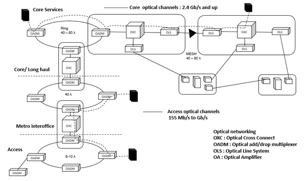
Initially, the need for optical layer bandwidth management will be the most acute in the core transport network environment. Here, logical mesh-based connectivity will be supported via physical topologies including OADM-based shared protection rings and OXC-based mesh restoration architectures. The choice will depend on the service provider's desired degree of bandwidth "over build" and survivability time scale requirements.
As similar bandwidth management requirements emerge for the metropolitan inter-office and access environments, OADM ring-based solutions will also be optimized for these applications: optical shared protection rings for mesh demands, and optical dedicated protection rings for hubbed demands. Hence, just as the OA was the technology enabler for the emergence of WDM point-to-point line systems, OADMs and OXCs will be the enablers for the emergence of the OTN.
As optical network elements assume the transport layer functionality traditionally provided by SDH equipment, the optical transport layer will come to serve as the unifying transport layer capable of supporting both legacy and converged packet core network signal formats. Of course, service provider movement to OTN will be predicted on the transfer of "SDH-like" transport layer functionality to the optical layer, concurrent with the development of a maintenance philosophy and associated network maintenance features for emerging optical transport layer.
Survivability is central to the role of optical networking as the unifying transport infrastructure. As with many other architectural aspects, optical network survivability will bear a high level resemblance to SDH survivability, since the network topologies and types of network elements are so similar. Within the optical layer, survivability mechanisms will continue to offer the fastest possible recovery from fiber cuts and other physical media faults, as well as provide efficient and flexible management of protection capacity.
OTN is conceptually analogous to SDH, in that sublayers are defined that reflect client-server relationships. Since, OTN and SDH are both connection-oriented multiplexed networks, it should not come as a surprise that the restoration and protection schemes for both are remarkably similar. The subtle but important difference is worth repeating: while TDM networking is based on digital time slot manipulation, OTN/WDM networking is based on analog frequency slot or optical channel (wavelength) manipulation. Thus, while we may expect similar protection and restoration architectures to be possible with both technologies, the types of the network failures for which one may need to account in any particular survivability scheme may be quite different.
Optical Layer Survivability
Telecommunication networks are required to provide reliable uninterrupted service to their customers. The overall availability requirements are of the order of 99.999 per cent or higher, which would imply that the network cannot be down for more than 6 min/year on average. As a result, network survivability is a major factor that affects how these networks are designed and operated. The networks need to be designed to handle link or fiber cuts as well as equipment faults.
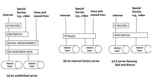
The network may be viewed as consisting of many layers inter-operating with each other, as shown in the above figure. Different carriers choose different ways of realizing their networks using different combinations of layering strategies. Incumbent carriers make use of their large installed base of SDH gear and the extensive grooming and monitoring capabilities of digital cross-connects.
In contrast, a carrier offering Internet Protocol (IP) based services seek to have a simplified network infrastructure using IP as the basic transport layer without using SDH. Carriers that distinguish themselves based on quality (and diversity) of services (QOS) may use ATM as their transport technology. Underneath these layers is the emerging optical WDM layer, or the optical layer.
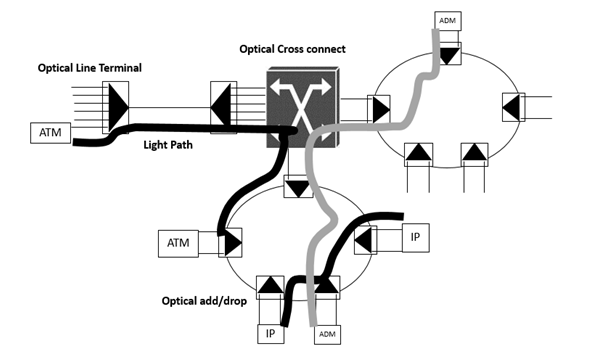
The optical layer provides light-paths to higher layers, which may be considered as client layers that make use of the service provided by the optical layer. Light paths are circuit-switched pipes carrying traffic at fairly high bit rates (e.g., 2.5 Gb/s or 10 Gb/s). These light paths are typically set up to interconnect client-layer equipment, such as SDH ADMs, IP routers, or ATM switches. Once they are set up, they remain fairly static over time.
The optical layer consists of Optical Line Terminals (OLTs), Optical ADMs (OADMs), and Optical Cross-Connects (OXCs) as shown in the following figure. OLTs multiplex multiple channels into a single fiber or fiber pair. OADMs drop and add small number of channels from/to an aggregate WDM stream. An OXC, switches and manages large number of channels in a high-traffic node location.
We look at the optical layer protection from a services perspective, in terms of the types of services needed to be provided by the optical layer to the higher layer. We then compare the different optical layer protection schemes that have been proposed in terms of their cost and bandwidth efficiency based on the service mix that must be supported. This is somewhat different, which tend to view optical layer protection as analogous to SDH layer protection.
Why Optical Layer Protection?
The IP, ATM, and SDH layers shown in the above figure, all incorporate protection and restoration techniques. While these layers were all designed to work with other layers, they can also directly operate over fiber, and thus do not depend on other layers to handle the protection and restoration functions. As a result, each of these layers incorporate its own protection and restoration functions. Thus, the question arises, why do we need the optical layer to provide its own set of protection and restoration mechanisms. Following are some of the reasons −
Some of the layers operating above the optical layer may not be fully able to provide all the protection functions needed in the network. For example, the SDH layer was designed to provide comprehensive protection and, therefore, would not rely on the optical layer protection. However, protection techniques in other layers (IP or ATM) by themselves may not be sufficient to provide adequate network availability in the presence of faults.
There are currently many proposals to operate the IP layer directly over the optical layer without using the SDH layer. While IP incorporates fault tolerance at the routing level, this mechanism is cumbersome and not fast enough to provide adequate QOS. In this case, it becomes important for the optical layer to provide fast protection to meet the overall availability requirements from the transport layer.
Most carriers have huge investments in legacy equipment that does not provide protection mechanisms at all, but cannot be ignored. A seamless introduction of the optical layer between this equipment and the raw fiber offers low-cost upgrade of the infrastructure over long fiber links with increased survivability.
Optical layer protection and restoration may be used to provide an additional level of resilience in the network. For example, many transport networks are designed to handle a single failure at a time, but not multiple failures. Optical restoration can be used to provide resilience against multiple failures.
Optical layer protection can be more efficient at handling certain types of failures, such as fiber cuts. A single fiber carries multiple wavelengths of traffic (e.g., 16-32 SDH streams). A fiber cut, therefore, results in all 16-32 of these SDH streams independently being restored by the SDH layer. The network management system is flooded with large number of alarms generated by each of these independent entities. If the fiber cut is restored sufficiently quickly by the optical layer, this operational inefficiency can be avoided.
Significant cost savings can be obtained by making use of optical layer protection and restoration.
Limitations - Optical Layer Protection
Following are some of the limitations of the optical layer protection.
It cannot handle all types of faults in the network. For example, it cannot handle the failure of a laser in an IP router or a SDH ADM attached to the optical network. This type of failure must be handled by the IP or SDH layer, respectively.
It may not be able to detect all types of faults in the network. The light paths provided by the optical layer may be transparent such that they carry data at a variety of bit rates. The optical layer in this case may in fact be unaware of what exactly is carried on these light paths. As a result, it cannot monitor the traffic to sense degradations, such as increased bit error rates, that would normally invoke a protection switch.
The optical layer protects traffic in units of light paths. It cannot provide different levels of protection to different parts of the traffic being carried on the light path (part of the traffic may be high-priority, the other lower priority). This function must be performed by a higher layer that handles traffic at this finer granularity.
There may be link budget constraints that limit the protection capability of the optical layer. For example, the length of the protection route or the number of nodes the protection traffic passes through may be constrained.
If the overall network is not carefully engineered, there may be race conditions when the optical layer and the client layer both try to protect traffic against a failure simultaneously.
The technology and protection techniques are yet to be field tested, and full scale deployment of these new protection mechanisms will, therefore, take a few years to happen.
Definitions of Protected Entities
Before going into the details of the protection techniques and the trade-offs between them, it is beneficial to define the entities that are protected by the optical layer and the client layer. These entities are shown in the following figure.
Client Equipment Port
The ports on the client equipment may fail. In this case, the optical layer cannot protect the client layer by itself.
Intrasite Connections Between the Client and the Optical Equipment
The cables inside a site may be disconnected, mainly due to human errors. This is considered a relatively likely event. Again, full protection against such occurrences can only be supported by combined client-layer and optical-layer protection.
Transponder Cards
Transponders are interface cards between the client equipment and the optical layer. These cards convert the signal from the client equipment into a wavelength that is suitable for use inside the optical network, using optical to electrical to optical conversion. Therefore, the failure rate of this card cannot be considered negligible. Given the large number of these cards in a system (one per wavelength), special protection support for them is in order.
External facilities
This fiber facility between the sites is considered the least reliable components in the system. Fiber cuts are fairly common. This category also includes optical amplifiers that are deployed along the fiber.
Entire nodes
An entire node can fail due to errors by maintenance staff (e.g., tripping power circuit breakers) or entire site failures. Site failures are relatively rare, and usually occur because of natural disasters such as fires, floods, or earthquakes. Node failures have a significant impact on the network and, therefore, still need to be protected against, despite their relatively low probability of occurrence.
Protection Vs Restoration
Protection is defined as the primary mechanism used to deal with a failure. It needs to be very fast (typically traffic should not be interrupted for more than 60 ms in the event of a failure of SDH networks). As a result, the protection routes usually need to be pre-planned so that traffic can be switched over from the normal routes on to the protection routes quickly.
Due to the speed requirements, this function is usually performed in a distributed way by the network elements without relying on a centralized management entity to coordinate the protection actions. With the exception of recent (and not yet proven) fast mesh protection schemes, the protection techniques tend to be fairly simple and are implemented in linear or ring topologies. They all end up using 100 percent access bandwidth in the network.
In contrast, restoration is not a primary mechanism used to deal with failure. After the protection function is complete, restoration is used to provide either efficient routes or additional resilience against further failures before the first failure is fixed. As a result, it can afford to be quite slow (seconds to minutes sometimes).
The restoration routes need not to be preplanned and can be computed on the fly by a centralized management system, without requiring a distributed control function. More sophisticated algorithms can be used to reduce the excess bandwidth required, and more complex mesh topologies can be supported.
Sublayers Within the Optical Layer
The optical layer consists of several sublayers. Protection and restoration can be performed at these different layers. We can have schemes that protect individual light paths or optical channels. These schemes handle fiber cuts as well as failure of terminal equipment, such as lasers or receivers.
We can have schemes that work at the aggregate signal level, which corresponds to the Optical Multiplex Section (OMS) layer. These schemes do not distinguish between different light paths that are multiplexed together, and restore all of them simultaneously by switching them as a group.
The term path-layer protection is used to denote schemes that operate over individual channels or light paths and line layer protection to denote schemes that operate at the optical multiplex section layer. Refer Table 1 for a comparison between the properties of path and line layer schemes, and Table 2 and Table 3 for the different path and line schemes.
Table 1: A Comparison Between Line Protection and Path Protection
| Criterion | Line Protection | Path Protection |
|---|---|---|
| Protects against | Interoffice facilities Site/node failures |
Interoffice facilities Site/node failures Equipment failures |
| Number of fibers | Four, if single-level multiplexing is used | Two |
| Can handle failures/degradation of a single path | No | Yes |
| Supports traffic that must not be protected | No | Yes |
| Equipment cost | Low | High |
| Bandwidth efficiency | Good for protected traffic | Low for unprotected channels |
Table 2: A Comparison Between Line-Layer Schemes
| Scheme | Protects Against | Topology | Constraints/ Deficiencies | Customer Benefits |
|---|---|---|---|---|
| 1+1 line | Line cuts | Point-to-point | Diverse route needed to protect fibers | Simplest to implement and operate |
| 1+1 line | Line cuts | Point-to-point | Diverse route needed to protect fibers | Support for low priority traffic Lower loss (by approx. 3 dB) |
| OULSR | Line cuts Node faults |
Metropolitan ring | Optical layer impairments Further power loss exists due to line-level bridging of signals |
Simple to implement and operate May be done using passive elements (instead of optical switches) |
| OBLSR | Line cuts Node faults |
Metropolitan ring | Optical layer impairments | Protection bandwidth reuse Support for low priority traffic |
| Mesh line Protection | Line cuts Node faults |
Any | Limited by optical layer impairments Based on all-optical cross-connect Hard to manage |
Efficient Low cost |
Table 3: A Comparison Between Path-Layer Schemes
| Scheme | Protects Against | Topology | Constraints/ Deficiencies | Customer Benefits |
|---|---|---|---|---|
| Client layer protection | Client equipment faults Intra-office facilities Transponder faults Interoffice facilities Node faults |
Any | Requires diverse paths in the network Most expensive |
Most extensive protection |
| 1:N equipment protection | Transponder faults | Linear or ring | Very low cost Bandwidth efficient |
|
| 1+1 path or OUPSR | Interoffice facilities Node faults |
Any | Requires diverse paths in the network Bandwidth consuming |
Similar to client protection Simple to develop and operate |
| OBPSR | Interoffice facilities Node faults |
Virtual ring | Protection bandwidth reuse Supports low priority traffic |
|
| Mesh path protection | Interoffice facilities Node faults |
Any | Requires an OXC Very complex to implement and operate |
High efficiency |
The physical network topology can be any mesh, passing light paths between the client equipment nodes. The virtual topology from the client equipment standpoint is restricted as per the client layer (e.g., rings for SDH). 2The physical topology is any mesh, while the virtual topology of the light paths is a ring.
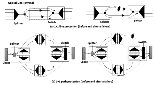
Consider, for example, the two protection schemes shown in the following figures. Both these schemes can be thought of as 1+1 protection schemes, that is, both split the signal at the transmit end and select the better copy at the receiving end. Fig. (a) depicts 1+1 line layer protection, in which both the splitting and selection is done for the entire WDM signal together. Fig. (b) depicts 1+1 path-layer protection, where splitting and selection are done separately for each light path.
Line Layer versus Path Layer Protection
There are important cost and complexity differences between the two approaches. Line protection requires one additional splitter and switch to an unprotected system. However, path protection requires one splitter and switch per channel. More importantly, path protection typically requires twice the transponders and twice the mux/demux resources of line protection. Therefore, path protection is almost twice as expensive as line protection, if all channels are to be protected. The story changes, however, if all the channels need not be protected.
The Basic Protection Schemes
A comparison of protection schemes can be found in Tables -1, 2, and 3. Optical layer protection schemes can be classified in much the same manner as SDH protection schemes and can be implemented at either the client layer, path layer, or line layer.
Client Protection
A simple option is to let the client layer take care of its own protection and not have the optical layer carry out any protection. This may be the case for SDH client layers. While this is simple from the optical layer's perspective, significant cost benefits and bandwidth savings can be obtained by performing optical layer protection. While the client protection method can support point-to-point, ring, or mesh client networks, it is important to note that from the optical network standpoint, all of these translate into optical mesh support, since even a point-to-point client link can span an entire optical mesh network.
In client layer protection, the working and protection client paths are fully diverse routed through the optical layer so that there are no single failure points. Also, the working and protection client paths should not be mapped on to different wavelength over the same WDM link. If WDM link fails, both paths would be lost.
Path Layer Schemes
1+1 Path Protection
This scheme requires two wavelengths across the network, as well as two sets of transponders at each end. When applied to a ring, this protection is also termed as Optical Unidirectional Path Switched Ring (OUPSR) or OCh Dedicated Protection Ring (OCh/DP Ring).
Implementation Notes − Bridging is typically done through an optical coupler, while selection is done via a 1 x 2 optical switch. The receiving end can decide to switch to the backup path without coordination with the source.
Bidirectional Path Switched Ring
This scheme is loosely based on the SDH 4-fiber Bidirectional Line Switched Ring (BLSR) and relies on shared protection bandwidth around the ring. When a working light path fails, the nodes coordinate and try to send the traffic through the designated protection bandwidth in the same direction around the ring (to overcome transponder faults). This is a span switch. If this fails, the nodes loop the traffic around the alternate path around the ring all the way to the other end of the failure. This action is a ring switch.
The scheme allows non-overlapping light paths to share the same protection bandwidth as long as they do not fail together. This scheme is also termed OCh shared protection ring (OCh/SPRing).
Implementation Notes − This scheme can be implemented in an OXC or, through much smaller switches in OADM. Switches are needed for each protection channel. It is similar to SDH BLSR standard.
Mesh Path Protection
This scheme allows global mesh protection with very fast switching (in less than 100 ms) for every failed light path separately to a backup path, shared by multiple light paths potentially taking a different route per light path. In case of a failure, it is intimated to all pertinent nodes that set up backup paths.
Implementation Notes − These schemes are being implemented in OXCs. Due to time constraints, predefined backup paths are stored in the nodes of the network and are activated based on failure types.
Mesh Path Restoration
Unlike mesh path protection, this scheme does not have stringent time constraints. This device computes alternate routes using its topology and disseminates a new setup information to the nodes, which set these routes up. The nodes do not need to maintain any n/w information.
Implementation Notes − The centralized nature of this scheme ensures more optimized protection routes and reduces the implementation and maintenance complexity.
1:N Equipment Protection
One of the most complex (and thus failure-prone) modules in a typical WDM terminal is a transponder. 1:N protection designates a spare transponder to take over in case the normal transponder fails.
Implementation Notes − This scheme more typically is based on a designated protected wavelength. In case of a failure, both ends have to switch using fast signaling protocols, not like APS in SDH.
Line Layer Schemes
1+1 Linear Protection
This scheme is based on bridging the entire WDM signal in bulk onto a pair of diversely routed facilities. The receiving end of these facilities then chooses which of the two signals to receive.
1:1 Linear Protection
This scheme requires a configuration similar to the previous one (i.e., 1+1 linear), however, the signal is switched to either the working or protection path, but not to both. While this increases the coordination burden, it allows running low-priority traffic on the back-up path (until it is needed to protect the working path). It also entails lower optical power loss due to the fact that the entire signal energy is directed to one path instead of two.
Implementation Notes − Switching is typically done using an optical 1×2 switch. Coordination is achieved through a fast-signaling protocol.
Optical Unidirectional Line Switching Ring (OULSR)
The scheme is similar to the OUPSR scheme except that the bridging and selection of signal is done for the aggregate WDM signal. This allows for a more optimized design, lower cost, and very different implementations.
Implementation Notes − An implementation of this scheme is based on passive couplers that run the optical ring into a broadcast medium. Instead of using OADMs, this scheme is based on simple OLTs, each coupled into both clockwise and counter-clockwise rings, so each of the wavelengths is transmitted and received on both fibers. Under normal condition, the link is artificially disconnected, resulting in a linear bus, when the fiber cut link is reconnected.
Bidirectional Line Switched Ring
This scheme is similar to the OBPSR scheme in both the protocol aspects and the protection actions used (span and ring switching). Like all line-layer schemes, the aggregate WDM signal is switched in bulk to a dedicated protect fiber (requiring four fibers), or to a different WDM band within a single fiber (allowing only two fibers, but requiring a two stage optical mux scheme). This scheme is also termed as OMS shared protection ring (OMS/SPRing).
Implementation Notes − As the backup route loops around the entire ring optically, optical line amplifiers may be needed along the backup path to compensate for the losses. The circumference of the ring is also limited by other optical impairments. Therefore, this option fits best in metropolitan applications.
Mesh Line Protection/Restoration
This scheme is based on all-optical cross-connects that divert the WDM signal from a failed facility on to an alternate route and back to the other end of failed facility.
Implementation Notes − Like OBLSR, this scheme is restricted by optical impairments that may develop along alternate routes and requires careful optical design.
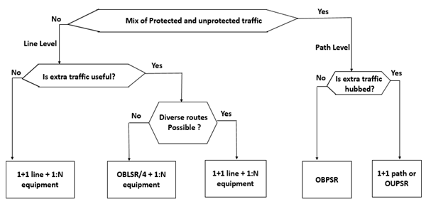
Consideration for the Choice of Protection Scheme
The criteria that could be used by a carrier to select the protection schemes to be used in the network. A simplified decision chart for this is depicted in the following figure assuming both equipment and line protection are needed.
The Cost of Protection
Another criterion from the carrier's standpoint is the cost of the system in at least two aspects −
- Equipment cost
- Bandwidth efficiency
Both of these depend on the service mix of the traffic, that is, the fraction of the traffic to be protected by the optical layer.
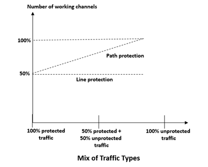
The following figure shows the equipment cost of path layer schemes and equivalent line-layer schemes as a function of the traffic mix. If all the traffic is to be protected, path layer schemes require about twice the equipment of the line-layer schemes as there is less sharing of common equipments.
However, the cost of path layer protection is proportional to the number of channels that are to be protected, as each channel requires an associated mux/demux and terminating equipment. Thus, the cost of path-layer protection drops if fewer channels have to be protected. In case where no channels need to be protected, path-layer schemes will cost about the same as line-layer schemes, assuming that no additional common equipment is deployed.
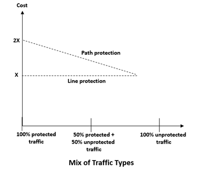
The story is different from the bandwidth efficiency standpoint, as shown in the following figure. In a line-protected system, the protection bandwidth is consumed for light paths that require protection as well as for those that do not require protection. In path-protection systems, light paths that do not require protection can use bandwidth, allowing other unprotected light paths to use bandwidth that would have been otherwise wasted on unwanted protection.
It follows that if a large portion of the light paths could be left unprotected, path-layer protection recuperates the cost by supporting more working traffic over the same network than line-layer protection.
Optical Networks - ROADM
Legacy optical networks deploy SDH/SONET technologies for transporting data across the optical network. These networks are relatively easy to plan and to engineer. New network elements can be easily added to the network. Static WDM networks may require less investment in equipment, especially in metro networks. However, the planning and maintenance of those networks can be a nightmare as engineering rules and scalability are often quite complex.
Bandwidth and wavelengths must be pre-allocated. As wavelengths are bundled in groups and not all groups are terminated at every node, access to specific wavelengths might be impossible at certain sites. Network extensions might require new Optical-Electrical-Optical regeneration and amplifiers or at least power adjustments in the existing sites. Operating static WDM network is manpower intensive.
Network and bandwidth planning should be as easy as in SDH/SONET networks in the past. Within the given ring bandwidth, for example STM-16 or OC-48 each node could provide as much bandwidth as needed.
Access to the entire bandwidth was possible at every ADM. Network extension, for example, introduction of a new node in an existing ring, was relatively easy and did not require any on-site visits of the existing nodes. The network diagram on the left illustrates this: Digital cross-connect systems link up with multiple optical SDH/SONET rings.
Reconfigurable optical networks act differently: Bandwidth can be planned on-demand and the reach is optimized as the optical power is now managed per WDM channel. The scalability goes up significantly.
The key element for enabling such a reconfigurable optical network is Reconfigurable Optical Add-drop Multiplexer (ROADM). It enables optical wavelengths to be redirected to client interfaces on just a click in the software. Other traffic remains unaffected by this. All this is achieved without needing any truck rolls to the respective sites to install filters or other equipment.
Reconfigurable WDM Network with ROADMs
Static WDM engineering rules and scalability can be quite complex (OADM in every node).
- Bandwidth and wavelength pre-allocation
- Margin allocation for fixed filter structure
- Insufficient power management
- Network extension requires Optical-Electrical-Optical (OEO) regeneration
SDH/SONET networks are easy to plan.
- Access to entire bandwidth at every ADM
- Easy engineering rules (single hop only)
- Easy addition of new network elements
A reconfigurable optical layer enables the following.
- On-demand bandwidth planning
- Extended transparent reach due to power management per WDM channel
- Hitless scalability
Static photonic layers consist of separate optical rings. Consider a number of DWDM systems located on each of these rings. Frequently information or data simply remains on the same ring, hence there is no issue. However, what happens in cases where data needs to be handed over to a different optical ring?
In static systems, a large number of transponders is required wherever a transition between rings is needed. Actually, each wavelength which passes from one ring to another needs two transponders: one on each side of the network. This approach incurs high costs and a lot of initial planning, considering the allocation of bandwidth and channels.
Let us now imagine a dynamic reconfigurable photonic layer. Here, there is only one single DWDM system forming the interface between two optical rings. Consequently, transponder-based regeneration disappears and the number of DWDM system drops. The whole network design is simplified and wavelengths can now travel from one ring to another without any further obstruction.
Any wavelength can propagate to any ring and to any port. The key to such a fully flexible and scalable network design, with an optical pass-through from the core right to the access area, is the ROADM and the GMPLS control plane.
Simplifications Through ROADMs
ROADMs provide simplifications in the network and in the service providers or carriers processes. This interaction summarizes some of these simplifications. After all, we need to bear in mind that all these advantages result in reduced time effort and cost. But what is more important is that they also lead to increased customer satisfaction and, in turn, customer loyalty.
Network planning is vastly simplified using ROADMs. Just consider the significantly reduced number of transponders, which need to be stocked in the warehouse.
Installation and commissioning for example, when setting up a new wavelength to the network require significantly less effort and are much less complex. Service technicians only need to visit the respective end sites to install the transponders and ROADM. Fixed Optical Add/Drop Multiplexers (FOADMs) used to require a visit to each intermediate site so that installation work and patches could be carried out.
Operations and maintenance are greatly simplified when a dynamic optical network is deployed. Optical diagnostics can be carried out in a few minutes rather than hours, as was previously the case. Impairments can be detected and dynamically cleared instead of triggering truck rolls to external sites.
With the deployment of tunable lasers and colorless ROADMs, the maintenance of the fiber plant is easier. Using these features, service provisioning is now easier than ever before. As with the installation and commissioning work, it is also significantly easier to perform network maintenance and any potential upgrades.
ROADM Architecture
Many advantages ROADMs bring to network design and operation were covered in the previous sections. Here are a few more −
- Per-channel power monitoring and leveling to equalize the entire DWDM signal
- Full traffic control from the remote network operation center
One question, however, has so far been left unanswered: How does a ROADM work? Lets take a look at some fundamentals.
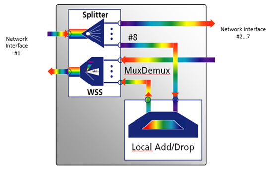
A ROADM generally consists of two major functional elements: A wavelength splitter and a wavelength selective switch (WSS). Take a look at the block diagram above: An optical fiber pair at network interface No. 1 is connected with the ROADM module.
The fiber carrying the incoming data (from the network) is fed to the wavelength splitter. Now, all the wavelengths are available at all output ports of the splitter, in this case 8. Local add/drop traffic (wavelengths) can be multiplexed/de-multiplexed with an Arrayed Waveguide Filter (AWG). Using an AWG implies a fixed wavelength allocation and direction.
The Wavelength Selective Switch (WSS) selectively joins the various wavelengths and feeds them to the output of network interface #1. The remaining splitter ports are connected with other network directions, for example, three other directions at a 4-degree junction node.
Note − One of the illustrated modules (completely grey box) is needed per network direction at this node. Or to be more precise: In a junction node serving four directions (4 degrees) four of these modules are needed.
The ROADM Heart the WSS Module
Lets start with the WDM signal coming in from the left. It passes through the optical fiber at the top and is directed towards a bulk diffraction grating. This bulk diffraction grating acts as a kind of prism. It separates the various wavelengths into different directions, though the variation in angle is pretty small. The separated wavelengths hit a spherical mirror, which reflects the rays onto a set of Micro-Electro Mechanical systems (MEMS) for short. Each micro switch is hit by a different wavelength, which is then sent back to the spherical mirror.
From there the rays are returned to the bulk diffraction grating and sent off to the optical fiber. But this is now a different fiber to the one we started with. The single wavelength output signal indicates that this has occurred. This signal can then be combined with other single wavelength signals to fill up another transmission fiber.
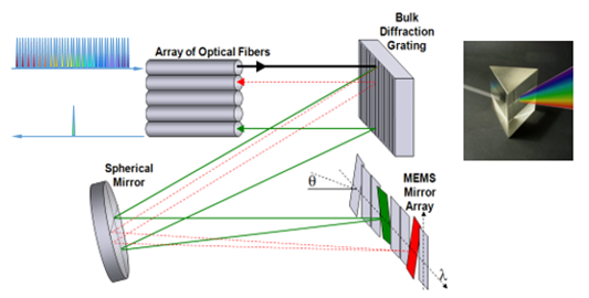
There are various versions available the keywords here are colorless, directionless, etc.
ROADM Degrees, Colorless, Directionless, and More
| Term | Explanation |
|---|---|
| Degree | The term Degree describes the number of supported DWDM line interfaces. A 2-degree ROADM node supports two DWDM line interfaces. It also allows two add/drop branches of all line interfaces. |
| Multi Degree | Multi degree ROADMs support more than two DWDM line interfaces. The number of possible add/drop branches is determined by the WSS port count. |
| Colorless | A colorless ROADM enables the flexible allocation of any wavelength or color to any port. Filter modules must be connected for implementing this function. |
| Directionless | A directionless ROADM does not require a physical reconnection of the transmission fibers. Restrictions on directions are eliminated. Directionless ROADMs are deployed for restoration purposes or the temporary re-routing of services (e.g. because of network maintenance or bandwidth on demand requirements). |
| Contentionless | Contentionless ROADMs eliminate the potential problem of two identical wavelengths colliding in the ROADM. |
| Gridless | Gridless ROADMs support various ITU-T channel grids with the same DWDM signal. The grid granularity can be adapted to future transmission speed requirements. |
To understand this leveled ROADM approach, following are some key terms often used in connection with ROADMs.
Colorless
Simple ROADMs comprise one WSS for each direction, also referred to as one degree. The wavelengths are still assigned and fixed add/drop transceivers used. Colorless ROADMs do away with this limitation: With such ROADMs any wavelength or color can be assigned to any port. No truck rolls are required as the complete setup is software-controlled. Filter modules must be implemented for realizing the colorless feature.
Directionless
This often appears in conjunction with the term colorless. A directionless design removes a further ROADM limitation. The need to physically reconnect the transmission fibers is eliminated using directionless ROADMs as there are no restrictions with regard to direction, for example, southbound or northbound.
Contentionless
Though colorless and directionless, ROADMs already offer great flexibility, two wavelengths using the same frequency could still collide in a ROADM. Contentionless ROADMs provide a dedicated internal structure to avoid such blocking.
Gridless
Gridless ROADMs support a very dense wavelength channel grid and can be adapted to future transmission speed requirements. The feature is required for signal rates of more than 100Gbit/s and different modulations formats within one network.
When Directionless
Directionless ROADMs are the most widely spread ROADM design as they allow the add/drop of a wavelength from the supported ITU grid on any line interface. In case of a directionless-only variant, the add/drop ports are specific to a defined wavelength. Using the colorless option, the ports can also be non-wavelength-specific.
The directionless technology is mostly deployed for re-routing wavelength to other ports as required for restoration purposes. Other applications are also possible, for example, in bandwidth-on-demand situations. ROADMs not supporting the directionless feature are subject to some limitations with regard to flexibility.
When Colorless
Colorless ROADMs allow the change of wavelengths of a specific optical channel without any physical re-cabling. A colorless ROADM can be reconfigured to add/drop any wavelength from the supported ITU grid on any add/drop port. The added/dropped wavelength can change (tunable DWDM interface). This enables −
Enhanced flexibility for wavelength provisioning and wavelength restoration
Restoration switching, directional switching, and color switching
The key advantage of colorless add/drop ports in combination with tunable DWDM line interfaces is the enhanced flexibility for wavelength provisioning and wavelength restoration purposes. Automatic tuning to next free wavelength on a requested optical path.
One of the last bits in fully automating the optical network is the deployment of colorless ROADMs. Using such ROADMs allows the add/drop of any wavelength of the supported ITU grid on any add/drop port. The wavelength on the port can change as tunable transceivers are used as optical frontends.
Wavelength provisioning and restoration is made even easier than before. Where a wavelength is busy, the system can automatically tune the transceiver to the next available free wavelength. ROADMs provide the option of using fixed and colorless add/drop features within the same ROADM node.
When Contentionless
Contentionless ROADMs can add/drop any wavelength at any add/drop port without any contention grid on any add/drop port. A dedicated wavelength color can be added/dropped multiple times (from different DWDM line interfaces) on the same add/drop branch. If only 8 add/drop ports are equipped, it must be possible to drop the same wavelength from 8 different line directions on the 8 add/drop ports. As long as free add/drop ports are available, the ROADM node must be able to add/drop any wavelength from/to any line interface.
The combination of Colorless, Directionless, and Contentionless functionality (CDC) provides the ultimate level of flexibility.
When Gridless
Gridless ROADM nodes support different ITU-T channel grids within the same DWDM signal. The grid bandwidth can be provisioned per channel.
The gridless feature is required for networks operating data rates beyond 100Gbit/s or for network operating with different modulation schemes. It is intended for next generation networks with coherent line interfaces. Different data rates demand different wavelength requirements depending on the modulation scheme and data rate.
Transmission speeds are going up and modulation schemes are becoming more and more complex. Several modulation technologies might now be mixed on a single optical fiber. All this reflects back to the ROADM technology and generates the requirements for gridless ROADMs. Such ROADMs operate on a dense frequency grid and allows a per-channel provisioning of the bandwidth. Data channels now demand different wavelengths requirements depending on their modulation scheme and their data rate.
Typical applications are networks operating with data rates beyond 100Gbit/s or running different modulation schemes in parallel. The latter situation can, for example, easily exist when deploying coherent transmission technologies.