
 Data Structure
 Networking
 RDBMS
RDBMS Operating System
 Java
Java MS Excel
 iOS
iOS HTML
HTML CSS
CSS Android
 Python
 C Programming
 C++
C++ C#
C# MongoDB
 MySQL
MySQL Javascript
 PHP
PHP
- Selected Reading
- UPSC IAS Exams Notes
- Developer's Best Practices
- Questions and Answers
- Effective Resume Writing
- HR Interview Questions
- Computer Glossary
- Who is Who
What is the BTIC scheme?
This scheme is only used occasionally, in cases when the taken penalty would be intolerable high due to a longer than I-cache latency. The basic idea of the BTIC scheme is to provide a small extra cache that delivers, for taken or predicted taken branches, the branch target instruction or a specified number of BTIs, rather than the BTA. Thus, otherwise unused pipeline cycles can be filled with target instructions.
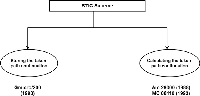
There are two alternatives implementations of the BTIC scheme, as shown in the figure. In the first, the address of the continuation of the taken path is also stored in the BTIC, whereas in the second it is dynamically calculated.
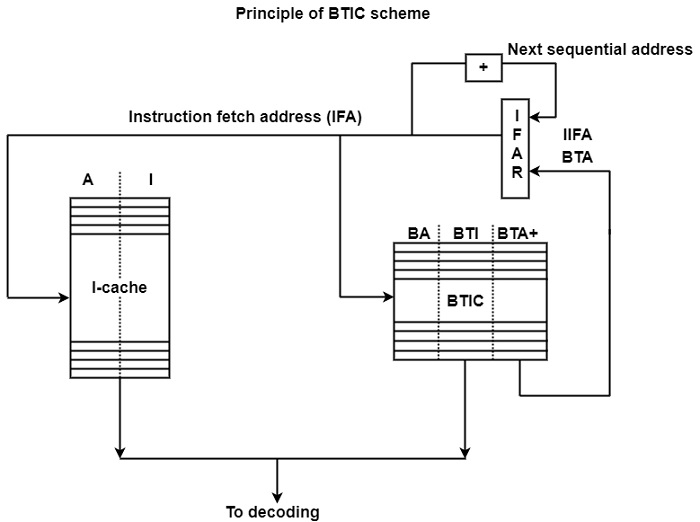
BTIC scheme with storing of the taken path continuation − The principle of this implementation is based on the Hitachi Gmicro/200 (1988) processor as shown in the figure. The Gmicro family of processors has been developed within the framework of the Japanese TRON project which was initiated in 1984. TRON is an open architecture defined at some layers, among others at the ISA layer (Sakamura, 1987a, 1987b).
TRON ISA is a CISC architecture. The Gmicro/200 is the first microprocessor that implements the TRON ISA specification. It is a scalar implementation using a six-stage CISC pipeline and an I-cache with a load latency of two cycles.
As shown in the figure, the BTIC contains entries consisting of three components. These are the addresses of currently taken branches (BA), the branch target instruction (BTI), and the addresses of the instructions following the BTIs (designates as BTA+).
When there is an entry in the BTIC for the actual instruction fetch address (IFA), the BTI is fetched from the BTIC and this instruction is selected for decoding, rather than the instruction being read directly from the I-cache. The address of the subsequent instruction along the taken path (BTA+) is also fetched from the BTIC. It becomes the next BTA. The BTIC contains only four entries.
BTIC four scheme with the calculation of the taken path continuation − The other variant of the BTIC scheme differs from the address of the taken path continuations are computed rather than stored in and read from the BTIC. The figure demonstrates this by showing how it is implemented in the MC 88110 processor.
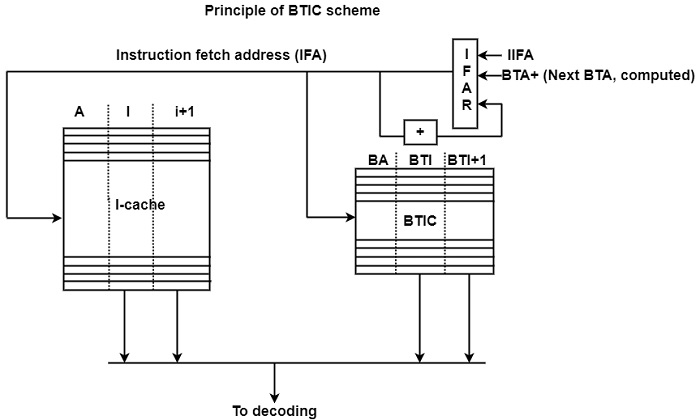
The BTIC includes triplets of addresses of the final currently taken branches (BA) as well as the first two instructions of the corresponding branch target path (BTI and BTI + 1).
When the BTIC includes an entry for the actual IFA, the corresponding two target instructions (BTI and BTI + 1) is fetched from the BTIC and selected for decoding rather than the two sequential instructions being read from the I-cache. The address of the taken path continuation (BTA+) is calculated from the BTA by incrementation and is used as the next IFA.

253 Views
