
Article Categories
- All Categories
-
 Data Structure
-
 Networking
-
 RDBMS
RDBMS
-
 Operating System
-
 Java
Java
-
 MS Excel
-
 iOS
iOS
-
 HTML
HTML
-
 CSS
CSS
-
 Android
-
 Python
-
 C Programming
-
 C++
C++
-
 C#
C#
-
 MongoDB
-
 MySQL
MySQL
-
 Javascript
-
 PHP
PHP
-
 Economics & Finance
Voltage in Series Circuits – Definition, Formula, Calculation, and Uses
In an electric circuit, when two or more electric circuit components are joined together in such a way that there is only one path for the flow of electric current, such connection of circuit components is referred to as series circuits. Therefore, in a series circuit, the current through all the circuit component remains the same, but the voltage across each element is different. In this article, we will discuss about the voltage in series circuits and how to calculate it.
What is Voltage in Series Circuits?
In a series circuit, the voltage across each element is different and depends upon the parameter of the component (for example resistance of the resistor). In order to understand the voltage in series, consider a resistive series circuit as shown in Figure-1.
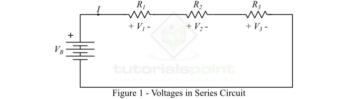
In this circuit, the current flowing through all the component is same, but the voltage across each element is different. Here, the battery provides energy to the electric charge to flow through the circuit. The voltage of across the battery is termed as emf (electromotive force). The voltage across resistors is referred to as the voltage drop. Thus, when an electric change pass through a battery, it gains energy, whereas when it pass through a resistor, it loses energy.
Therefore, when an electric charge (considering conventional direction) starts its journey from positive terminal of the battery, let it have V volts energy. When it passes through resistor ?1, a part of energy of the charge is lost due to its resistance, let it is ?1 volts. Similarly, when it passes through resistors ?2 and ?3 it lost ?2 and ?3 volts respectively.
According to the law of energy conservation, it is known that for an electric charge, the energy gained and energy lost during its journey must be equal.
$$\mathrm{\therefore V_{B}=V_{1}+V_{2}+V_{3}}$$
Where, the value of ?1, ?2, and ?3 can be given by Ohm?s law as follows ?
$$\mathrm{V_{1}=IR_{1}}$$
$$\mathrm{V_{2}=IR_{2}}$$
$$\mathrm{V_{3}=IR_{3}}$$
From the above example of series circuit, it is clear that the voltage in a series circuit is simply the algebraic sum of voltages across the different elements of the circuit.
Connection of DC Voltage Sources in Series
We can connect several direct voltage sources in series to obtain a higher DC voltage. Direct voltage sources are connected in series as shown in Figure-2. The total voltage of the series combination is equal to the sum of voltages of all the voltage sources.
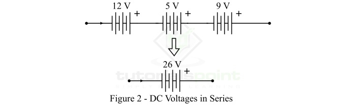
In this case, the total voltage of the series combination of dc voltage sources is given by,
$$\mathrm{V = 12 + 5 + 9 = 26 V}$$
Connection of AC Voltage Sources in Series
We can also connect the ac voltage (alternating voltage) sources in series to obtain a higher alternating voltage. While connecting alternating voltage sources in series always remember that the angular frequency (?) of all the alternating voltage sources must be identical. Also, we may join several alternating voltage sources having different frequencies in series, but in this the current through all the voltage sources must be same.
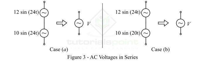
In this case, the total voltage of the series combination of the alternating voltage sources is given by,
$$\mathrm{V= 22\: sin(24t)\: \cdot \cdot \cdot (a)}$$
$$\mathrm{V= 12 \: sin 24t + 10 \: sin 20t \: \cdot \cdot \cdot (b)}$$
Connection of DC and AC Voltage Sources in Series
We may also connect DC voltage sources and ac voltage sources in series provided that the current through all the sources connected in series must remain the same. An example of series combination of a DC voltage source and an ac voltage source is shown in Figure-4.

The total voltage of the series combination of DC and DC voltage sources is given by,
$$\mathrm{V= 12 + 10\: sin 10t}$$
Application of Voltages in Series
In actual practice, the voltages in series are used in several electrical and electronic systems and devices. Some of them are listed below ?
Batteries are connected in series in remotes, toys, etc.
Cells are connected in series to make a battery.
Voltage divider circuit is an example of voltages in series circuits.
A battery powered torch light circuit is also an example voltage in series circuit, in which a lamp is connected across a battery through a resistor.
Conclusion
From the above discussion, it is clear that the total voltage supplied by the source is shared among all the circuit elements connected in series. The sum of all voltages in series is equal to the sum of total source voltage. When we need a high voltage, we simply connect different voltage sources in series to obtain the desired voltage.

1K+ Views
