
 Data Structure
 Networking
 RDBMS
RDBMS Operating System
 Java
Java MS Excel
 iOS
iOS HTML
HTML CSS
CSS Android
 Python
 C Programming
 C++
C++ C#
C# MongoDB
 MySQL
MySQL Javascript
 PHP
PHP
- Selected Reading
- UPSC IAS Exams Notes
- Developer's Best Practices
- Questions and Answers
- Effective Resume Writing
- HR Interview Questions
- Computer Glossary
- Who is Who
The Adafruit.io
Adafruit.io is needed to display the IOT project's data online in real-time. It is a cloud server that can be used to connect to IoT devices through wifi and to control these devices through a dashboard. It can be used as a free service and it has got a simple easy-to-use interface to design dashboards. The key for authentication can be generated directly from the user's account and can be included in the program to connect the IOT components to the respective dashboard. The feeds are important to make connections, using the program that connects the IOT circuit to the Adafruit dashboards. The feeds are holders for the data and related information that is transferred to and fro from the dashboard and IOT circuit.
In this article, using a simple example, the process of connecting IoT devices to an online dashboard made using Adafruit.io is given. The connection is made using wifi.
The Steps to make the connection between IOT devices and Adafruit Dashboard:
Step 1 ? Make the circuit diagram using ESP32, a BMP180 sensor, and an LED of blue color.
Step 2 ? Write a program in C on Arduino IDE.
Step 3 ? Open https://io.adafruit.com/ and Signup. Login to the account and fetch the key.
Step 4 ? Set the feeds for temperature, pressure, altitude, and blue light and then make a dashboard and set the layout for these feeds.
Step 5 ? Connect the circuit to the computer using a USB data cable and run the program.
Step 6 ? Check the result using Serial Monitor and also check the readings on the dashboard.
Setting the feeds on Adafruit.io
Settings of the feeds for temperature, pressure, altitude, and the bluelight on Adafruit.io are given below. These will be connected to the Adafruit.io dashboard and also to BMP180 sensor readings and a blue LED.
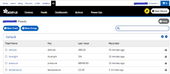
Fig 1: Feeds needed to connect the dashboard and IOT device data.
Making the Circuit
Connect the BMP180 sensor to ESP32. Connect SCL to D22 and SDA to D21 of ESP32. Also, connect a blue LED using the D18 pin of ESP32. Connect GND to the negative rail and Vin to the positive rail. Connect 3v3 of ESP32 to the positive rail and GND of ESP32 to the negative rail.
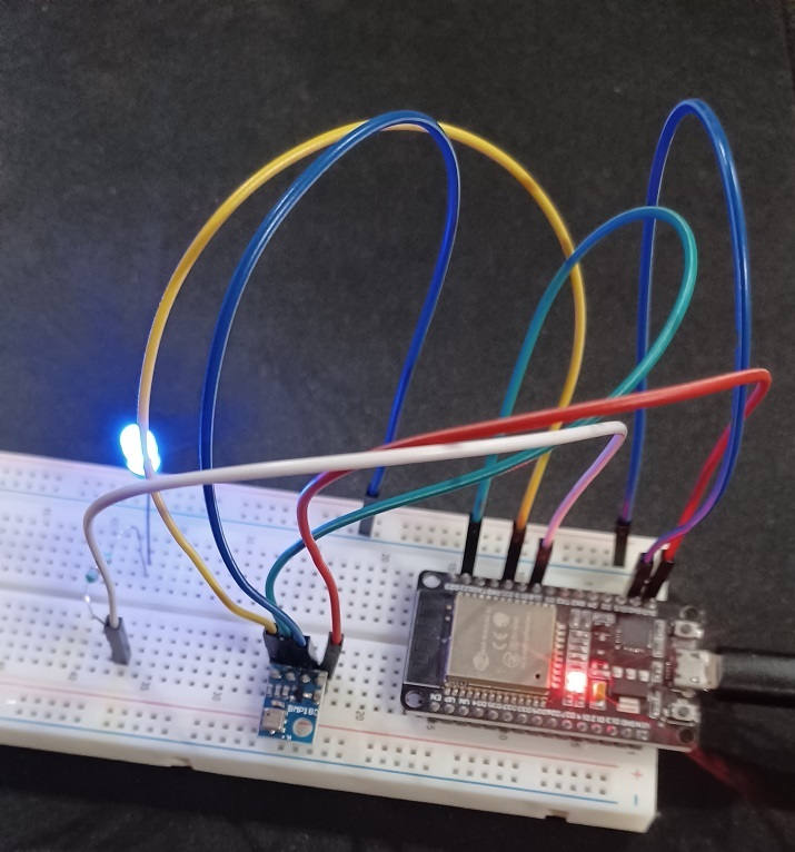
Fig 2: Circuit diagram for Adafuit.io project.
Writing The Code
Write the C language program on Arduino IDE. The Code is given below ?
// Required library to make the connection of Arduino board through internet
#include <WiFi.h>

//required for using BMP180 sensor
#include <Adafruit_BMP085.h>
//required message queue telemetry transport protocol to subscribe and publish feeds
#include "Adafruit_MQTT.h"
#include "Adafruit_MQTT_Client.h"

/************************* WiFi Access Point *********************************/
//use your own SSID and password
#define WLAN_SSID    "Write SSID Here"
#define WLAN_PASS    "Write Wifi Password here"

/************************* Adafruit.io Setup *********************************/
// the adafruit server to connect
#define AIO_SERVER    "io.adafruit.com"

// the port to connect
#define AIO_SERVERPORT 1883

// get this key from your own Adafruit Account
#define AIO_USERNAME "Write your Adafruit IO username here"
#define AIO_KEY "Write Your Adafruit IO key here"

WiFiClient wclient;

Adafruit_MQTT_Client mqtt(&wclient, AIO_SERVER, AIO_SERVERPORT, AIO_USERNAME, AIO_KEY);

//Feeds Settings

//temperature value that will be read through BMP180 sensor
Adafruit_MQTT_Publish temperature = Adafruit_MQTT_Publish(&mqtt, AIO_USERNAME "/feeds/temperature");

//pressure value that will be read through BMP180 sensor
Adafruit_MQTT_Publish pressure = Adafruit_MQTT_Publish(&mqtt, AIO_USERNAME "/feeds/pressure");

//altitude value that will be read through BMP180 sensor
Adafruit_MQTT_Publish altitude = Adafruit_MQTT_Publish(&mqtt, AIO_USERNAME "/feeds/altitude");

// Setup a feed called 'bluelight' for subscribing to changes.
Adafruit_MQTT_Subscribe bluelight = Adafruit_MQTT_Subscribe(&mqtt, AIO_USERNAME "/feeds/bluelight");

void MQTT_connect();

const int BLUE_LED = 18;

float t;
float p;
float a;

String stringOne;

Adafruit_BMP085 bmpObj;

void setup() {
   Serial.begin(9600);
   delay(10);

   pinMode(BLUE_LED, OUTPUT);
   digitalWrite(BLUE_LED, LOW);

   Serial.println("Adafruit MQTT demo");

   // Connect to WiFi access point.
   Serial.println(); Serial.println();
   Serial.print("Connecting to ");
   Serial.println(WLAN_SSID);

   WiFi.begin(WLAN_SSID, WLAN_PASS);
   while (WiFi.status() != WL_CONNECTED) {
      delay(500);
      Serial.print(".");
   }
   Serial.println();

   Serial.println("WiFi connected");
   Serial.println("IP address: "); Serial.println(WiFi.localIP());

   // Setup MQTT subscription for bluelight feed.
   mqtt.subscribe(&bluelight);
   if (!bmpObj.begin()) {
      Serial.println("BMP180 Sensor not detected ! ! !");
      while (1) {}
   }
}
uint32_t x = 0;

void loop() {
   t = bmpObj.readTemperature();
   p = bmpObj.readPressure();
   a = bmpObj.readAltitude();
   // a = bmpObj.readAltitude(102000);
   Serial.println(t);
   Serial.println(p);
   Serial.println(a);

   delay(100);

   MQTT_connect();

   Adafruit_MQTT_Subscribe *subscription;
   while ((subscription = mqtt.readSubscription(5000))) {
      if (subscription == &bluelight) {
         Serial.print("Got: ");
         Serial.println((char *)bluelight.lastread);
         digitalWrite(BLUE_LED, HIGH);

         stringOne = (char *)bluelight.lastread;
         Serial.print("stringOne: ");
         Serial.println(stringOne);

         if (stringOne == "ON") {
            digitalWrite(BLUE_LED, HIGH);
         }
         if (stringOne == "OFF") {
            digitalWrite(BLUE_LED, LOW);
         }
      }
   }
   if (! temperature.publish(t)) {
      Serial.println("Temperature measure Failed");
   } else {
      Serial.println("Temperature measure OK!");
   }
   if (! pressure.publish(p)) {
      Serial.println("pressure measure Failed");
   } else {
      Serial.println("pressure measure OK!");
   }
   if (! altitude.publish(a)) {
      Serial.println("Altitude measure Failed");
   } else {
      Serial.println("Altitude measure OK!");
   }
}
void MQTT_connect() {
   int8_t retvar;
   if (mqtt.connected()) {
      return;
   }
   Serial.print("Connecting to MQTT... ");
   uint8_t trytimes = 3;
   while ((retvar = mqtt.connect()) != 0) {
      Serial.println(mqtt.connectErrorString(retvar));
      Serial.println("retrying MQTT connection in 5500 mseconds...");
      mqtt.disconnect();
      delay(5500); // wait 5 seconds
      trytimes--;
      if (trytimes == 0) {
         while (1);
      }
   }
}
Viewing The Result - On the Adafruit.io Dashboard
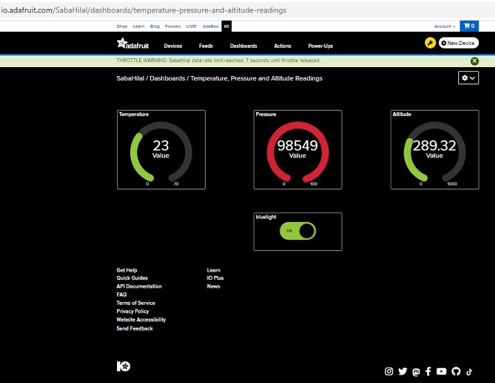
Fig 3: Showing the Dashboard on Adafruit.io with BMP180 sensor readings and LED control button.
Viewing The Result - On the Serial Monitor
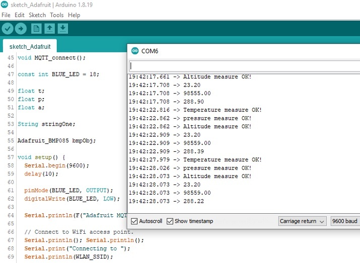
Fig 4: Showing the result as seen on Serial Monitor while running the program.
In this article, using the BMP180 sensor, an LED, and ESP32, the ways to use Adafruit.io is given. First, the circuit is made. Then log in to Adafruit.io and create the feeds and then make a dashboard on Adafuit using feeds. Then a program is written using C on Arduino IDE and it is run to view the result on the Adafuit dashboard as well as on Serial Monitor.

2K+ Views
