
 Data Structure
 Networking
 RDBMS
RDBMS Operating System
 Java
Java MS Excel
 iOS
iOS HTML
HTML CSS
CSS Android
 Python
 C Programming
 C++
C++ C#
C# MongoDB
 MySQL
MySQL Javascript
 PHP
PHP
- Selected Reading
- UPSC IAS Exams Notes
- Developer's Best Practices
- Questions and Answers
- Effective Resume Writing
- HR Interview Questions
- Computer Glossary
- Who is Who
Successive approximation ADC interface
The Model ALS-NIFC-07 which on approximating successfully ADC is clearly described in this topic. It consists of a programmable timer interface which connects to the kit of ALS-SDA-85M by using a flat cable of 26 crores. The connector C1 gets connected to the interface by the Input Output connector P3 in the kit for the ALS, which is implemented on a flat cable. The power supply of +12V, -12V, +5V, and GND gets connected to the interface. The circuit description is shown below –
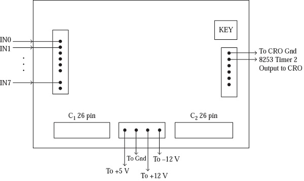
C1 is connected to connector P3 (or P4) on ALS kit, for ADC interface purpose
C2 is connected to connector P2 on ALS kit, for timer interface
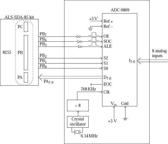
If we consider ADC 0809, then it is an 8-bit ADC. The interface uses a crystal oscillator, which provides 768 kHz as the clock input to the ADC 0809. The conversion takes 64 clocks (about 100 μs). ADC 0809 has eight analog inputs (I7-0). One of them is selected by S2, S1, S0 inputs, which are driven by PB2, PB1, and PB0 of 8255.
The address on S2, S1, S0 gets latched by ADC 0809 when the input ALE becomes 1. If a ‘0’ is sent out on PB5 of 8255 the input ALE of ADC 0809 turns to 1.
To start the conversion, SOC (start of conversion) should become a 1. This is achieved by sending a 0 on PB6. Then the EOC (end of conversion) output of the ADC becomes a 1. After the conversion is over, EOC output is made 0 by the ADC. So, after the SOC signal is provided, we have to wait for at least 100 μs, for the conversion to be over.
Then the digital output D7-0, corresponding to the selected Analog input, comes out on the ADC output pins if the OE (output enable) input of the ADC is at logic 1. The OE input of ADC becomes logic 1, if logic 0 is sent out on PB7. Then 8085 reads this digital value from Port A and displays it in the data field of the 8085 kit. When using this interface, it is required to configure the 8255 ports on the kit as follows.
PA as input PB as output PC as input
PC in not used by the successive approximation ADC interface. Port addresses for 8255 connected to connector P3 are as follows.
Port A: D8H Port B: D9H Port C: DAH Control: DBH
It is possible to connect the second 8255 on the ALS kit to the ADC interface. For this purpose, I/O connector P4 on the ALS kit is connected to the interface, using the 26-core flat cable. Port addresses for the second 8255 on the ALS kit are:
Port A: F0H Port B: F1H Port C: F2H Control: F3H

694 Views
