
 Data Structure
 Networking
 RDBMS
RDBMS Operating System
 Java
Java MS Excel
 iOS
iOS HTML
HTML CSS
CSS Android
 Python
 C Programming
 C++
C++ C#
C# MongoDB
 MySQL
MySQL Javascript
 PHP
PHP
- Selected Reading
- UPSC IAS Exams Notes
- Developer's Best Practices
- Questions and Answers
- Effective Resume Writing
- HR Interview Questions
- Computer Glossary
- Who is Who
Status check data transfer in 8085
Status check data transfer process is a much more complex process than simple data transfer. We use this method is used when there is lack of accurate knowledge of the Input Output device consisting of the timing characteristics. Status information is received by the processor regarding the readiness of the Input Output device for performing the data transfer. Generally, the processor is involved in the checking of the loop for the device to get ready. The device releases from the loop when the device is ready for use for the execution of the IN or OUT instruction which depends on the requirement. The flowchart shown below will help us to know the entire process for the simple Input Output process.

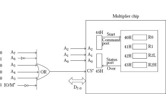
The pins of Address A2, A1, and A0 always selects a register as shown below.
|
A2 |
A1 |
A0 |
Selected Register |
|---|---|---|---|
| 0 |
0 |
0 |
R0 |
| 0 |
0 |
1 |
R1 |
| 0 |
1 |
0 |
R2L (LS Byte of Product) |
| 0 |
1 |
1 |
R2H (MS Byte of Product) |
| 1 |
0 |
0 |
Command register |
| 1 |
0 |
1 |
Status register |
Let us say the chip which is connected as the mapping of I/O mapped Input Output, as shown in the fig below. As per the circuit of the chip selection the address for R0, R1, R2L, R2H, command register and status register is 40H, 41H, 42H, 43H, 44H and 45H respectively.
Along with the setup process, the following segment of program which performs the multiplication of 05H and 08H, and the result gets stored in the BC register pair.

523 Views
