
 Data Structure
 Networking
 RDBMS
RDBMS Operating System
 Java
Java MS Excel
 iOS
iOS HTML
HTML CSS
CSS Android
 Python
 C Programming
 C++
C++ C#
C# MongoDB
 MySQL
MySQL Javascript
 PHP
PHP
- Selected Reading
- UPSC IAS Exams Notes
- Developer's Best Practices
- Questions and Answers
- Effective Resume Writing
- HR Interview Questions
- Computer Glossary
- Who is Who
RIM instruction in 8085
In 8085 Instruction set, Read Interrupt Mask. It is a 1-Byte multi-purpose instruction. It is used for the following purposes.
To check whether RST7.5, RST6.5, and RST5.5 are masked or not;
To check whether interrupts are enabled or not;
To check whether RST7.5, RST6.5, or RST5.5 interrupts are pending or not;
To perform serial input of data.
| Mnemonics, Operand |
Opcode (in HEX) |
Bytes |
|---|---|---|
| RIM |
20 |
1 |
To get the status information about the interrupt system, Read Interrupt Mask instruction provides status information about interrupt system and this instruction can be used for serial input of data. Through this RIM instruction, 8085 can know which interrupt is masked or unmasked, etc. The contents of the Accumulator after the execution of the RIM instruction provide this information.
Thus, it is essential to look into the Accumulator contents after the Read Interrupt Mask instruction is executed. The meaning of the various bits of the Accumulator after Read Interrupt Mask is executed is shown in the following figure –
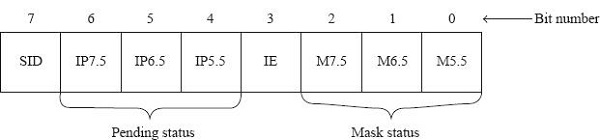
Mask status of interrupts: The LS 3 bits of the accumulator are used to provide mask status of interrupts. Note that they are not used for masking or unmasking. Masking or unmasking has to be done using the Read Interrupt Mask instruction.
| Bit No. |
Purpose |
|---|---|
| Bit 0: |
This is mask RST5.5 (M5.5) bit.
|
| Bit 1: |
This is mask RST6.5 (M6.5) bit.
|
| Bit 2: |
This is mask RST7.5 (M7.5) bit.
|
Interrupt Enable (IE) status: Bit 3 of the Accumulator provides the status of IE flip-flop after the Read Interrupt Mask instruction is executed.
If IE = 1, it means that the interrupt system is enabled. This will be the situation if EI instruction is executed sometime prior to the RIM instruction.
If IE = 0, it means that the interrupt system is disabled. This will be the situation if sometime prior to execution of the RIM instruction, one of the following things have occurred.
DI instruction was executed
Intel 8085 has been reset
Intel 8085 has entered an interrupt service subroutine.
Let us now other status bits in the following table –
| Bit No. |
Purpose |
|---|---|
| Bit 4: |
This is interrupt pending RST5.5 (IP5.5) bit.
|
| Bit 5: |
This is interrupt pending RST6.5 (IP6.5) bit.
|
| Bit 6: |
This is interrupt pending RST7.5 (IP7.5) bit.
|
8085 Microprocessor is having one pin labelled Serial Input Data. Which is required for serial data communication. 1-bit of information can be read by the Microprocessor at each single clock pulse. So most significant bit of the Accumulator receives the data present on the SID pin of 8085 when the RIM instruction is executed. In view of this, the meaning of bit 7 of the Accumulator will be as follows, after we execute the RIM instruction.
| Bit No. |
Purpose |
|---|---|
| Bit 7: |
This is SID bit. After the RIM instruction is executed, the data on the SID pin of 8085 gets loaded into this bit position. |
Let us discuss details about the various interrupts of 8085 as summarized in the table that follows.
| Pin |
Priority |
Interrupt Service Sub-routine Address |
Sensitivity |
Condition |
|---|---|---|---|---|
| TRAP |
Highest |
0024H |
RisingEdge and High Level |
Unconditional |
| RST7.5 |
Second |
003CH |
RisingEdge |
Unmasked and EI |
| RST6.5 |
Third |
0034H |
High Level |
Unmasked and EI |
| RST5.5 |
Fourth |
002CH |
High Level |
Unmasked and EI |
| INTR |
Lowest |
Supplied by an external device |
High Level |
EI |
Let us consider the following program segment –
| Address |
Hex Codes |
Mnemonic |
Comment |
|---|---|---|---|
| 2000 |
3E |
MVI A, 19H |
A ← 19H =0001 1001, it means SOD=0, SDE=0, R7.5=1, MSE=1, M5.5=1 |
| 2001 |
19 |
|
Accumulator value 19H |
| 2002 |
30 |
SIM |
Set Interrupt Mask |
| 2003 |
20 |
RIM |
Read Interrupt Mask. If Accumulator gets the value01H then that means SID=0, I7.5=0, I6.5=0, I5.5=0, IE=0, M7.5=0,M6.5=0 and M5.5=1 |
The timing diagram against this instruction Read Interrupt Mask execution is as follows –
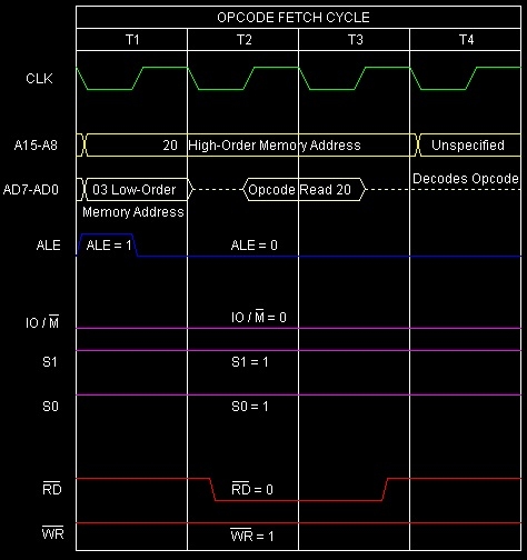
Summary − So this instruction Read Interrupt Mask requires 1-Byte, 1-Machine Cycle (Opcode Fetch) and 4 T-States for execution as shown in the timing diagram.

6K+ Views
