- Physics - Home
- Physics - Force and Pressure
- Physics - Friction
- Physics - Some Natural Phenomena
- Physics - Motion
- Physics - Force and Laws of Motion
- Physics - Gravitation
- Physics - Mass and Weight
- Physics - Work and Energy
- Physics - Light
- Physics - Reflection and Refraction
- Images Formed by Spherical Mirrors
- Physics - Refraction of Light
- Physics - Spherical Lenses
- The Human Eye & Colorful World
- Refraction of Light Through a Prism
- Physics - Electricity
- Chemical Effects of Electric Current
- Magnetic Effects of Electric Current
- Physics - Electric Motor
- Physics - Source of Energy
- Physics - Sound Part I
- Physics - Sound Part II
- Speed of Sound in Different Media
- Physics - The Solar System
- Physics - Stars and The Solar System
Physics - Electricity
Introduction
If the electric charge flows through a conductor, such as a metallic wire, it is known as the electric current in the conductor.
A continuous and closed path of an electric current is known as an electric circuit (as shown in the image given below) −
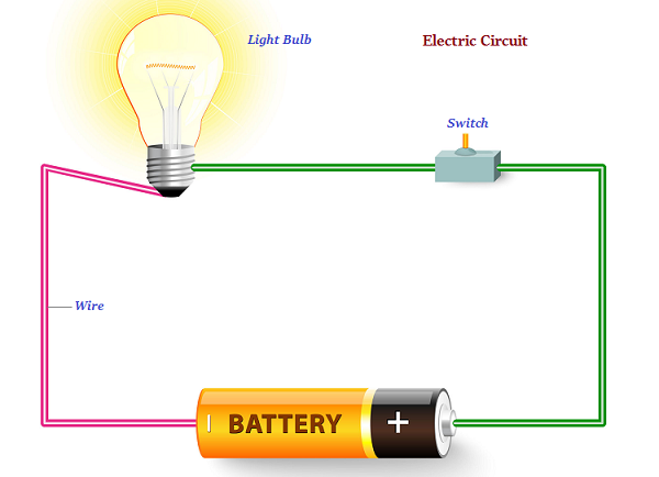
In an electric circuit, usually, the direction of electric current (known as positive charges), is considered as opposite to the direction of the flow of electrons, which are considered as negative charges.
The SI unit of electric charge is coulomb (C).
Coulomb is equivalent to the charge contained in closely 6 × 10¹⁸ electrons.
The electric current is expressed by a unit known as an ampere (A).
It was named after the French scientist Andre-Marie Ampere.
One ampere constitutes by the flow of one coulomb of charge per second, i.e., 1 A = 1 C/1 s.
The instrument that measures electric current in a circuit is known as ammeter.
The electric current flows in the circuit starting from the positive terminal to the negative terminal of the cell through the bulb and ammeter.
Electric Potential and Potential Difference
The electrons of a conductor move only if there is a difference of electric pressure, known as the potential difference.
The chemical action within a cell produces the potential difference across the terminals of the cell. Further, when this cell is linked to a conducting circuit element, the potential difference sets the charges in motion (in the conductor) and generates an electric current.
Alessandro Volta (17451827), an Italian physicist, first noticed the electric potential difference; therefore, the SI unit of electric potential difference is given volt (V).
The instrument that measures the potential difference is known as the voltmeter.
Circuit Diagram
Some defined symbols are used to illustrate the most commonly used electrical components in circuit diagrams.
The following table describes some of the symbols commonly used to define the electric components −
| Components | Symbols |
|---|---|
| An electric cell |  |
| A battery or combination of cells |  |
| Plug key or switch (Open) | 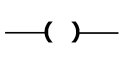 |
| Plug key or switch (closed) | 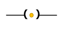 |
| A wire joint | 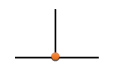 |
| Wires crossing without joining |  |
| Electric bulb |  |
| A resistor of resistance R | 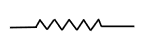 |
| Variable resistance or rheostat | 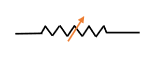 |
| Ammeter | 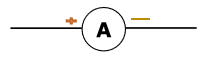 |
| Voltmeter | 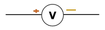 |
Ohms Law
A German physicist, Georg Simon Ohm in 1827, stated that The electric current flowing through a metallic wire is directly proportional to the potential difference (V), across its ends provided its temperature remains the same.
Electric Power
The rate at which electric energy is dissipated or consumed in an electric circuit is known as electric power.
The SI unit of electric power is watt (W).