
 Data Structure
 Networking
 RDBMS
RDBMS Operating System
 Java
Java MS Excel
 iOS
iOS HTML
HTML CSS
CSS Android
 Python
 C Programming
 C++
C++ C#
C# MongoDB
 MySQL
MySQL Javascript
 PHP
PHP
- Selected Reading
- UPSC IAS Exams Notes
- Developer's Best Practices
- Questions and Answers
- Effective Resume Writing
- HR Interview Questions
- Computer Glossary
- Who is Who
Intel 8257 Programmable DMA Controller
As per DIP package Intel 8257 DMA controller chip is a 40-pin programmable Integrated Circuit. The pin diagrams of physical and functional are indicated below. The DMA controller chip 8257 works in two modes namely −
- Slave Mode and
- Master Mode.
Likely the processor also works in two modes namely active mode and HOLD mode. The processor normally works in active mode where the processor works as the master of the computer system. The processor goes to the HOLD state only when DMA transfer is required and it gives control to the system bus.
When the processor is programming 8257 it is in slave mode. But at the time of reading the internal memory of the register it is in active mode and becomes the master of the computer system.
8257 is used to control the DMA data transfer since it consists of four I/O ports. Every I/O port corresponds to a DMA channel. There is a DMA request called as DRQ input for every DMA channel, which corresponds DMA acknowledge as output. Amidst each DMA channel consists of 16-bit address register and 16-bit count register.
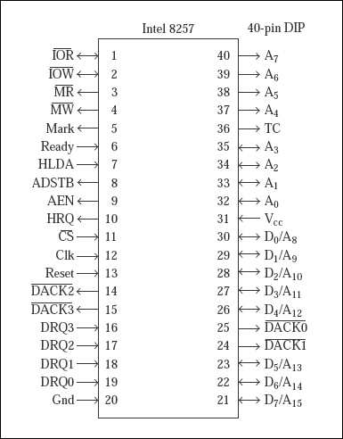
Fig. Physical pin diagram of Intel 8257
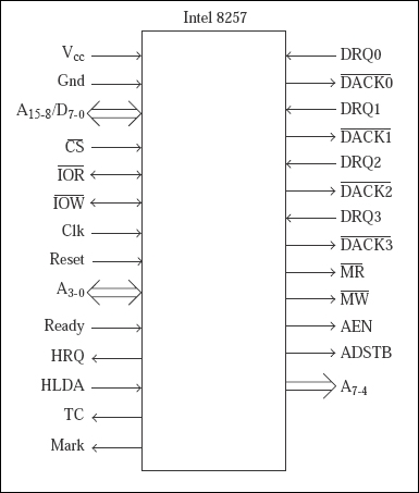
Fig: Functional pin diagram of Intel 8257
For performing the DMA data operation, DMA channel has two lines HOLD and HLDA. When the I/O port needs MA service, it activates an input DRQ of 8257, which sends the Hold Request HRQ of 8085. The 8085 completes the current machine cycle and goes to the HOLD state. In this state the address pins and data pins like RD*, WR*, and IO/M* pins are tristate and attached. So the 8085 is effectively disconnected from the rest of the system.

824 Views
