
Article Categories
- All Categories
-
 Data Structure
-
 Networking
-
 RDBMS
RDBMS
-
 Operating System
-
 Java
Java
-
 MS Excel
-
 iOS
iOS
-
 HTML
HTML
-
 CSS
CSS
-
 Android
-
 Python
-
 C Programming
-
 C++
C++
-
 C#
C#
-
 MongoDB
-
 MySQL
MySQL
-
 Javascript
-
 PHP
PHP
Flip-flop types and their Conversion in C++
Flip-Flops are sequential digital circuits. There are few different types of flip-flops. Here we will see the types of flip-flops and the conversion rules from one flip-flop to another.
There are basically four types of flip-flops −
- SR Flip-Flop
- D Flip-Flop
- JK Flip-Flop
- T Flip-Flop
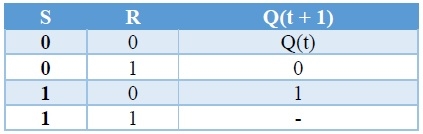
SR Flip-flop
SR flip-flop operates with only positive clock transitions or negative clock transitions. Whereas, SR latch operates with enable signal. The circuit diagram of SR flip-flop is shown in the following figure.
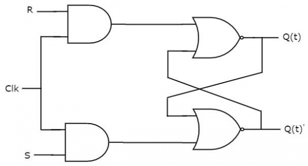
This circuit has two inputs S & R and two outputs Q(t) & Q(t)’. The operation of SR flipflop is similar to SR Latch. But, this flip-flop affects the outputs only when a positive transition of the clock signal is applied instead of active enable.
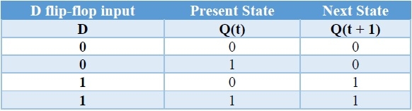
D Flip-flop
D flip-flop operates with only positive clock transitions or negative clock transitions. Whereas, D latch operates with enable signal. That means the output of D flip-flop is insensitive to the changes in the input, D except for active transition of the clock signal. The circuit diagram of the D flip-flop is shown in the following figure.
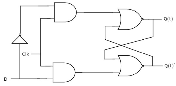
This circuit has single input D and two outputs Q(t) & Q(t)’. The operation of the D flip-flop is similar to D Latch. But, this flip-flop affects the outputs only when a positive transition of the clock signal is applied instead of active enable.

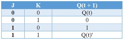
JK Flip-flop
JK flip-flop is the modified version of SR flip-flop. It operates with only positive clock transitions or negative clock transitions. The circuit diagram of JK flip-flop is shown in the following figure
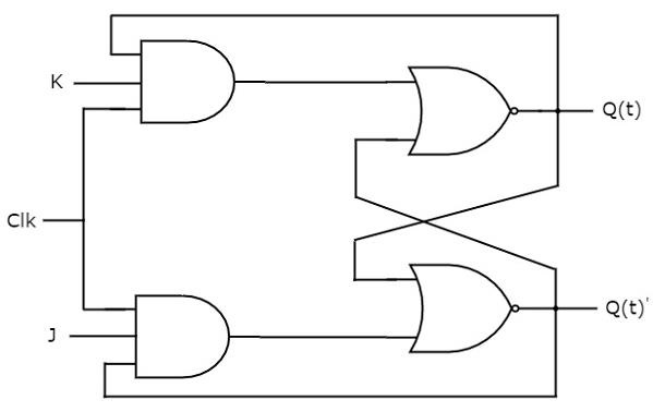
This circuit has two inputs J & K and two outputs Q(t) & Q(t)’. The operation of JK flip-flop is similar to SR flip-flop. Here, we considered the inputs of SR flip-flop as S = J Q(t)’ and R = KQ(t) in order to utilize the modified SR flip-flop for 4 combinations of inputs.
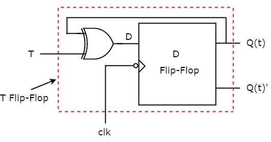
T Flip-flop
T flip-flop is the simplified version of JK flip-flop. It is obtained by connecting the same input ‘T’ to both inputs of JK flip-flop. It operates with only positive clock transitions or negative clock transitions. The circuit diagram of T flip-flop is shown in the following figure.
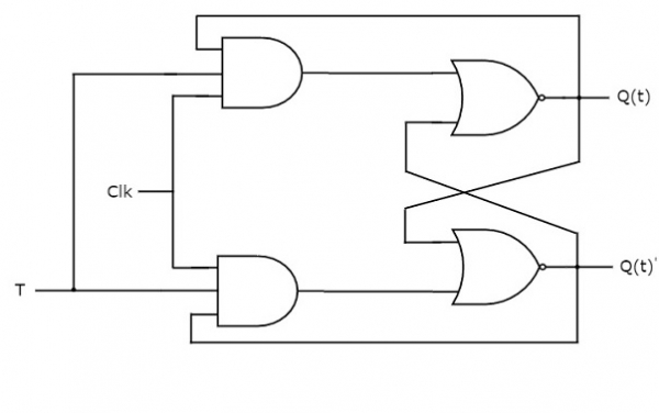
This circuit has a single input T and two outputs Q(t) & Q(t)’. The operation of T flip-flop is the same as that of JK flip-flop. Here, we considered the inputs of JK flip-flop as J = T and K = T in order to utilize the modified JK flip-flop for 2 combinations of inputs. So, we eliminated the other two combinations of J & K, for which those two values are a complement to each other in T flip-flop.

Flip-Flop Conversions
Now we will see how to convert from one flip-flop to another. At first we will see the excitation table for all flip-flops.
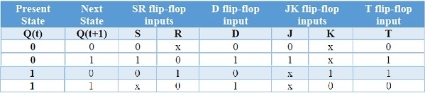
SR Flip-flop to D Flip-flops
Here, the given flip-flop is SR flip-flop and the desired flip-flop is D flip-flop. Therefore, consider the following characteristic table of D flip-flop.
We know that SR flip-flop has two inputs S & R. So, write down the excitation values of SR flip-flop for each combination of present state and next state values. The following table shows the characteristic table of D flip-flop along with the excitation inputs of SR flip-flop.
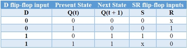
We can use 2 variable K-Maps for getting simplified expressions for these inputs. The k-Maps for S & R are shown below.
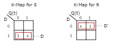
So, we got S = D & R = D' after simplifying. The circuit diagram of D flip-flop is shown in the following figure.
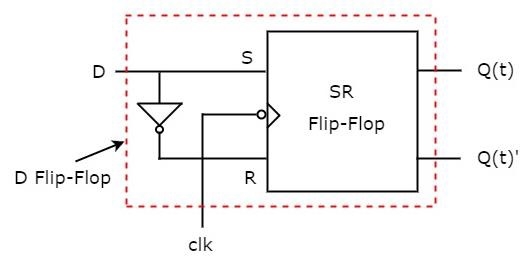
This circuit consists of SR flip-flop and an inverter. This inverter produces an output, which is complement of input, D. So, the overall circuit has single input, D and two outputs Q(t) & Q(t)'. Hence, it is a D flip-flop. Similarly, you can do other two conversions.
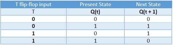
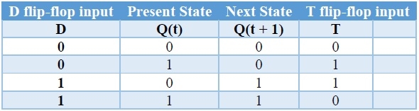
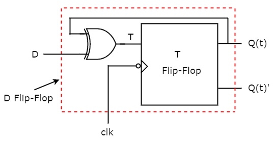
D Flip-flop to T Flip-flops
Here, the given flip-flop is D flip-flop and the desired flip-flop is T flip-flop. Therefore, consider the following characteristic table of T flip-flop.
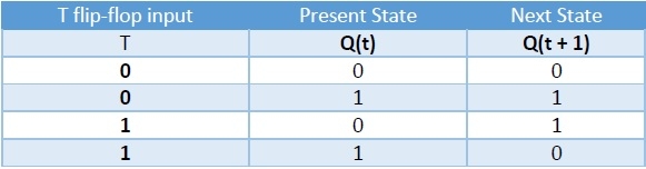
We know that D flip-flop has single input D. So, write down the excitation values of D flip-flop for each combination of present state and next state values. The following table shows the characteristic table of T flip-flop along with the excitation input of D flip-flop.
From the above table, we can directly write the Boolean function of D as below. So, we require a two input Exclusive-OR gate along with D flip-flop. The circuit diagram of T flip-flop is shown in the following figure.
This circuit consists of D flip-flop and an Exclusive-OR gate. This Exclusive-OR gate produces an output, which is Ex-OR of T and Q(t). So, the overall circuit has single input, T and two outputs Q(t) & Q(t)’. Hence, it is a T flip-flop. Similarly, you can do other two conversions.
JK Flip-flop to T Flip-flops
Here, the given flip-flop is JK flip-flop and the desired flip-flop is T flip-flop. Therefore, consider the following characteristic table of T flip-flop.
We know that JK flip-flop has two inputs J & K. So, write down the excitation values of JK flip-flop for each combination of present state and next state values. The following table shows the characteristic table of T flip-flop along with the excitation inputs of JK flipflop.
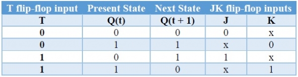
We can use 2 variable K-Maps for getting simplified expressions for these two inputs. The k-Maps for J & K are shown below.
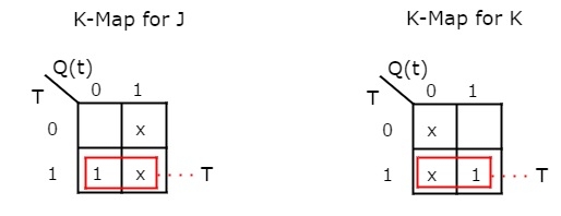
So, we got, J = T & K = T after simplifying. The circuit diagram of T flip-flop is shown in the following figure.
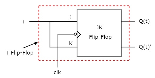
This circuit consists of JK flip-flop only. It doesn’t require any other gates. Just connect the same input T to both J & K. So, the overall circuit has single input, T and two outputs Q(t) & Q(t)’. Hence, it is a T flip-flop. Similarly, you can do other two conversions.
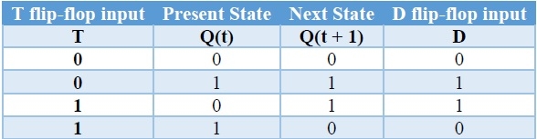
T Flip-flop to D Flip-flops
Here, the given flip-flop is T flip-flop and the desired flip-flop is D flip-flop. Therefore, consider the characteristic table of D flip-flop and write down the excitation values of T flip-flop for each combination of present state and next state values. The following table shows the characteristic table of D flip-flop along with the excitation input of T flip-flop.
So, we require a two input Exclusive-OR gate along with T flip-flop. The circuit diagram of D flip-flop is shown in the following figure.
This circuit consists of T flip-flop and an Exclusive-OR gate. This Exclusive-OR gate produces an output, which is Ex-OR of D and Q(t). So, the overall circuit has single input, D and two outputs Q(t) & Q(t)’. Hence, it is a D flip-flop. Similarly, you can do other two conversions.

2K+ Views
