
 Data Structure
 Networking
 RDBMS
RDBMS Operating System
 Java
Java MS Excel
 iOS
iOS HTML
HTML CSS
CSS Android
 Python
 C Programming
 C++
C++ C#
C# MongoDB
 MySQL
MySQL Javascript
 PHP
PHP
- Selected Reading
- UPSC IAS Exams Notes
- Developer's Best Practices
- Questions and Answers
- Effective Resume Writing
- HR Interview Questions
- Computer Glossary
- Who is Who
Execution of ‘DAD rp’ instruction
In 8085 Instruction set, for 16-bit addition, there is one instruction available that is DAD rp instruction. It is a 1-Byte instruction. With this instruction, with the content of the HL register pair, the contents of the mentioned register pair will get added and the result thus produced will be stored on the HL register pair.
| Mnemonics, Operand |
Opcode(in HEX) |
Bytes |
|---|---|---|
| DAD B |
09 |
1 |
| DAD D |
19 |
1 |
| DAD H |
29 |
1 |
| DAD SP |
39 |
1 |
As an example, let us consider the execution of the DADB instruction. Let us suppose, that the initial content of HL register pair is 5050H and content of BC register pair is 4050H. So now if we execute instruction DAD B then the following 16-bit addition will take place –
| Before |
After |
|
|---|---|---|
|
(BC) |
4050H |
4050H |
|
(HL) |
5050H |
90A0H |
|
Calculation Steps |
(BC)= 4050H = 0100 0101 (HL)= 5050H = 0101 0101 ----- --------- (HL) 90A0H = 1001 1010 |
|
In the first machine cycle M1, the opcode 09H for DAD B instruction is fetched from the memory into the IR register of 8085. Then this instruction will be decoded by the 8085 to interpret it as the opcode for DAD B instruction. This Opcode Fetch machine cycle takes a total of 3 + 1 = 4 clock cycles. Now it is the time to add the contents of HL and BC register pairs and storing the result on toHL register pair. In 8085 we have only an 8-bit ALU. So to perform this 16-bit addition, we take support from temp registers to hold intermediate results.
In the second machine cycle M2, the following actions take place.
Accumulator is temporarily stored in the W register;
L register contents are moved to the Accumulator;
C register contents are moved to the temp register;
Addition is performed, and ALU output is moved to the L register.
This machine cycle uses up three clock cycles. It is aBus Idle (BI) machine cycle because:
No address is sent out by 8085;
No data is sent out or received from outside;
No external control signals are generated by 8085.
In the third machine cycle M3, the following actions take place.
H register contents are moved to the Accumulator;
B register contents are moved to the temp register;
Addition with Cy is performed, and the result stored is in H;
Accumulator gets the original value from the W register.
This machine cycle uses up three clock cycles. This is also a Bus Idle (BI) machine cycle because:
No address is sent out by 8085;
No data is sent out or received from outside;
No external control signals are generated by 8085.
Thus, DAD B instruction needs a total of ten clock cycles. It consists of Opcode Fetch machine cycle (four clock cycles), followed by two BI machine cycles (each of three clock cycles).
| Address |
Hex Codes |
Mnemonic |
Comment |
|---|---|---|---|
| 2000 |
D3 |
OUT F0H |
Accumulator content will be sent to port addressF0H |
| 2001 |
F0 |
F0H as port address |
The timing diagram against this instruction OUT F0H execution is as follows –
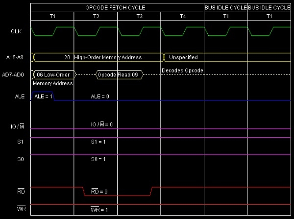
Summary − So this instruction OUT requires 1-Byte1, 3-Machine Cycles (Opcode Fetch, Bus Idle Cycle, BusIdle Cycle) and 10 T-States for execution as shown in the timing diagram.

2K+ Views
