- Digital Electronics - Home
- Digital Electronics Basics
- Types of Digital Systems
- Types of Signals
- Logic Levels And Pulse Waveforms
- Digital System Components
- Digital Logic Operations
- Digital Systems Advantages
- Number Systems
- Number Systems
- Binary Numbers Representation
- Binary Arithmetic
- Signed Binary Arithmetic
- Octal Arithmetic
- Hexadecimal Arithmetic
- Complement Arithmetic
- Base Conversions
- Base Conversions
- Binary to Decimal Conversion
- Decimal to Binary Conversion
- Binary to Octal Conversion
- Octal to Binary Conversion
- Octal to Decimal Conversion
- Decimal to Octal Conversion
- Hexadecimal to Binary Conversion
- Binary to Hexadecimal Conversion
- Hexadecimal to Decimal Conversion
- Decimal to Hexadecimal Conversion
- Octal to Hexadecimal Conversion
- Hexadecimal to Octal Conversion
- Binary Codes
- Binary Codes
- 8421 BCD Code
- Excess-3 Code
- Gray Code
- ASCII Codes
- EBCDIC Code
- Code Conversion
- Error Detection & Correction Codes
- Logic Gates
- Logic Gates
- AND Gate
- OR Gate
- NOT Gate
- Universal Gates
- XOR Gate
- XNOR Gate
- CMOS Logic Gate
- OR Gate Using Diode Resistor Logic
- AND Gate vs OR Gate
- Two Level Logic Realization
- Threshold Logic
- Boolean Algebra
- Boolean Algebra
- Laws of Boolean Algebra
- Boolean Functions
- DeMorgan's Theorem
- SOP and POS Form
- POS to Standard POS Form
- Minimization Techniques
- K-Map Minimization
- Three Variable K-Map
- Four Variable K-Map
- Five Variable K-Map
- Six Variable K-Map
- Don't Care Condition
- Quine-McCluskey Method
- Min Terms and Max Terms
- Canonical and Standard Form
- Max Term Representation
- Simplification using Boolean Algebra
- Combinational Logic Circuits
- Digital Combinational Circuits
- Digital Arithmetic Circuits
- Multiplexers
- Multiplexer Design Procedure
- Mux Universal Gate
- 2-Variable Function Using 4:1 Mux
- 3-Variable Function Using 8:1 Mux
- Demultiplexers
- Mux vs Demux
- Parity Bit Generator and Checker
- Comparators
- Encoders
- Keyboard Encoders
- Priority Encoders
- Decoders
- Arithmetic Logic Unit
- 7-Segment LED Display
- Code Converters
- Code Converters
- Binary to Decimal Converter
- Decimal to BCD Converter
- BCD to Decimal Converter
- Binary to Gray Code Converter
- Gray Code to Binary Converter
- BCD to Excess-3 Converter
- Excess-3 to BCD Converter
- Adders
- Half Adders
- Full Adders
- Serial Adders
- Parallel Adders
- Full Adder using Half Adder
- Half Adder vs Full Adder
- Full Adder with NAND Gates
- Half Adder with NAND Gates
- Binary Adder-Subtractor
- Subtractors
- Half Subtractors
- Full Subtractors
- Parallel Subtractors
- Full Subtractor using 2 Half Subtractors
- Half Subtractor using NAND Gates
- Sequential Logic Circuits
- Digital Sequential Circuits
- Clock Signal and Triggering
- Latches
- Shift Registers
- Shift Register Applications
- Binary Registers
- Bidirectional Shift Register
- Counters
- Binary Counters
- Non-binary Counter
- Design of Synchronous Counter
- Synchronous vs Asynchronous Counter
- Finite State Machines
- Algorithmic State Machines
- Flip Flops
- Flip-Flops
- Conversion of Flip-Flops
- D Flip-Flops
- JK Flip-Flops
- T Flip-Flops
- SR Flip-Flops
- Clocked SR Flip-Flop
- Unclocked SR Flip-Flop
- Clocked JK Flip-Flop
- JK to T Flip-Flop
- SR to JK Flip-Flop
- Triggering Methods:Flip-Flop
- Edge-Triggered Flip-Flop
- Master-Slave JK Flip-Flop
- Race-around Condition
- A/D and D/A Converters
- Analog-to-Digital Converter
- Digital-to-Analog Converter
- DAC and ADC ICs
- Realization of Logic Gates
- NOT Gate from NAND Gate
- OR Gate from NAND Gate
- AND Gate from NAND Gate
- NOR Gate from NAND Gate
- XOR Gate from NAND Gate
- XNOR Gate from NAND Gate
- NOT Gate from NOR Gate
- OR Gate from NOR Gate
- AND Gate from NOR Gate
- NAND Gate from NOR Gate
- XOR Gate from NOR Gate
- XNOR Gate from NOR Gate
- NAND/NOR Gate using CMOS
- Full Subtractor using NAND Gate
- AND Gate Using 2:1 MUX
- OR Gate Using 2:1 MUX
- NOT Gate Using 2:1 MUX
- Memory Devices
- Memory Devices
- RAM and ROM
- Cache Memory Design
- Programmable Logic Devices
- Programmable Logic Devices
- Programmable Logic Array
- Programmable Array Logic
- Field Programmable Gate Arrays
- Digital Electronics Families
- Digital Electronics Families
- CPU Architecture
- CPU Architecture
Parallel Adder and Parallel Subtractor
In digital electronics, adder and subtractor are the two most basic arithmetic combinational circuits. The adder is a combinational arithmetic circuit used to perform addition of two or more binary numbers. Whereas, the subtractor is a combination arithmetic circuit used to perform subtraction of two binary numbers.
Depending on the form in which the addition and subtraction of binary numbers are executed, the adder and subtractor are classified into following types −
- Serial Adder
- Parallel Adder
- Serial Subtractor
- Parallel Subtractor
This tutorial is meant for explaining Parallel Adder and Parallel Subtractor. But before that let us first discuss the rules of Boolean algebra followed to perform the binary addition and subtraction.
Binary Addition
The following rules are followed while performing binary addition −
| Binary Digit A | Binary Digit B | Sum (A + B) | Carry |
|---|---|---|---|
| 0 | 0 | 0 | 0 |
| 0 | 1 | 1 | 0 |
| 1 | 0 | 1 | 0 |
| 1 | 1 | 0 | 1 |
Binary Subtraction
The following rules are to be followed while performing binary subtraction −
| Binary Digit A | Binary Digit B | Difference (A - B) | Borrow |
|---|---|---|---|
| 0 | 0 | 0 | 0 |
| 0 | 1 | 1 | 1 |
| 1 | 0 | 1 | 0 |
| 1 | 1 | 0 | 0 |
Now, let us discuss the parallel adder and parallel subtractor in detail.
What is Parallel Adder?
A digital circuit that adds two binary numbers of any bit length in parallel form and produces the sum of those number in parallel form is called a parallel adder.
A parallel adder basically consists of full adders in a chain form as shown in Figure 1. Here, the output bit of each full adder is connected to the input carry terminal of the next full adder circuit in the chain.
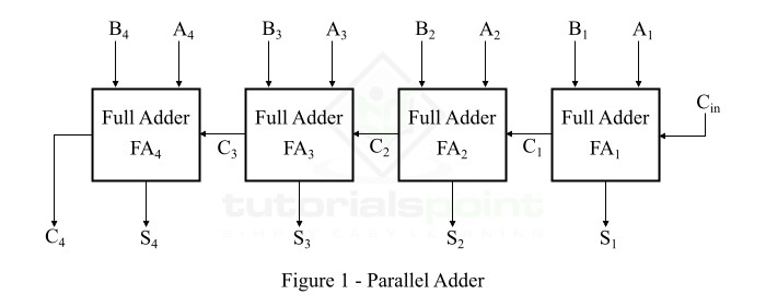
The parallel adder shown in Figure 1 is a 4-bit parallel adder as it can add two binary number of 4 bits. Although, we can design a parallel adder circuit for any number of bits by increasing the number of full adders in the chain.
In the above parallel adder circuit, the bit A is representing the augend bits and B is representing the addend bits. The first input carry bit to the parallel adder is Cin and the output carry bit of the parallel adder is C4. The output sum bits are designated by S. We can also construct a parallel adder in the form of an IC. For example, when the 4-bit parallel adder is formed in the IC form, then it will have four terminals for augend bits, 4 terminals for addend bits, 4 terminals for sum bits, and 2 terminals for input and output carry bits.
Working of Parallel Adder
The parallel adder shown in figure-1 performs the binary addition of two numbers as per the following step −
Step 1 − Firstly, the full adder circuit FA1 adds the bits A1 and B1 along with the input carry bit Cin to produce the sum bit S1, where it is the LSB (Least Significant Bit) of the output sum. At this stage, a carry bit C1 is generated which is transferred to the next full adder circuit in the chain.
Step 2 − The full adder circuit FA2 adds bits A2 and B2 along with the carry bit C1 from the previous addition. It produces the sum bit S2 which is the second bit of the output sum, and a carry bit C2 is also produced which again forwarded to the next full adder FA3.
Step 3 − The full adder circuit FA3 adds inputs bits A3 and B3 along with the carry bit C2 from previous addition to produce sum bit S3 and carry bit C3.
Step 4 − The full adder FA4 adds input bits A4 and B4 along with the carry bit C3 forward from FA3. It generates the last sum bit S4 and a last carry bit C4.
Step 5 − The output sum of the parallel adder is then given by,
$$\mathrm{S_{out} \: = \: C_{4} \: S_{4} \: S_{3} \: S_{2} \: S_{1}}$$
What is Parallel Subtractor?
A digital arithmetic circuit which is used to find the arithmetic difference of two binary numbers in parallel form is called a parallel subtractor.
We can implement a parallel subtractor in several ways such as combining half subtractors and full subtractors, all full subtractors, all full adders, etc. Here, we have realized a 4-bit parallel subtractor using all full adders with subtrahend bit complemented as shown in Figure 2.
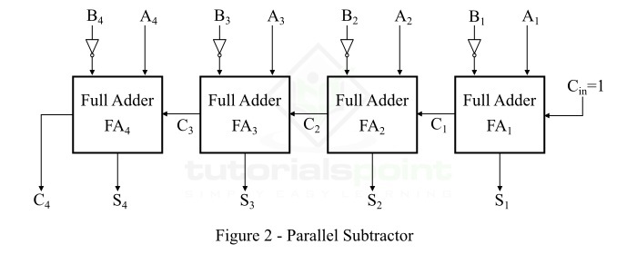
This is the 4-bit parallel subtractor, however, we can implement a parallel subtractor by adding any number of full adders in the chain of the circuit shown in figure-2.
The binary subtraction of two binary numbers can be conveniently accomplished by means of 1's or 2's complement. Where, the complement method converts the subtraction operation in simple addition operation.
The 2's complement of binary numbers is obtained by taking the 1's complement and adding 1 to the least significant pair of bits. The 1's complement can be implemented with the help of a NOT gate (inverter).
Working of Parallel Subtractor
The parallel subtractor shown in above figure-2 carries out the subtraction of two binary numbers as per the following steps −
Step 1 − Firstly, the 1's complement of bit B1 obtained using an inverter and a 1 (Cin) are added to obtain the 2's complement of the bit B1. Then, this 2's complemented B1 is further added to A1. This will produce first bit of the output difference designated by S1, and a carry bit C1 which is connected to the input carry of the FA2.
Step 2 − The full adder FA2 uses the input carry bit C1 to add with its input bit A2 and the 2's complement of the input bit B2 to produce the second difference bit (S2) and the carry bit C2.
Step 3 − The full adder FA3 uses the input carry bit C2 to add with its input bit A3 and the 2's complement of the input bit B3 to produce the third difference bit (S3) and the carry bit C3.
Step 4 − Finally, the full adder FA4 uses the carry bit C3 to add with its input bit A4 and the 2's complement of the input bit B4 to produce the last difference bit (S4) and last carry bit C4.
Once all the result bits are produced, they are expressed to give the difference of the two binary numbers as S4S3S2S1 and borrow bit C4.
Conclusion
This is all about parallel adder and parallel subtractor in digital electronics. The most significant advantage of the parallel adder and subtractor is that they perform the arithmetic addition and subtraction of two binary numbers faster as compared to the serial adder and subtractor.